
 | ||
The IBM 1620 was announced by IBM on October 21, 1959, and marketed as an inexpensive "scientific computer". After a total production of about two thousand machines, it was withdrawn on November 19, 1970. Modified versions of the 1620 were used as the CPU of the IBM 1710 and IBM 1720 Industrial Process Control Systems (making it the first digital computer considered reliable enough for real-time process control of factory equipment).
Contents
- The 1620 architecture
- Character and op codes
- Invalid character
- Architectural difficulties
- Software
- Operating procedures
- Console
- Paper Tape readerpunch
- Card readerpunch
- Disk drives
- General
- Hardware implementation
- A computer for the small scientific market
- Requirements and design
- The prototype
- Transferred to San Jose for production
- Implementation levels
- Related peripheral units
- Notable Uses
- Use in film and television
- References
Being variable word length decimal, as opposed to fixed-word-length pure binary, made it an especially attractive first computer to learn on — and hundreds of thousands of students had their first experiences with a computer on the IBM 1620.
Core memory cycle times were 20 microseconds for the Model I, 10 microseconds for the Model II (about a thousand times slower than typical computer main memory in 2006).
Many in the user community recall the 1620 being referred to as CADET, jokingly meaning "Can't Add, Doesn't Even Try", referring to the use of addition tables in memory rather than dedicated addition circuitry. For an explanation of all three known interpretations of the machine's code name see the section on the machine's development history.
The 1620 architecture
It was a variable "word" length decimal (BCD) computer with a memory that could hold anything from 20,000 to 60,000 decimal digits increasing in 20,000 decimal digit increments. (While the 5-digit addresses could have addressed 100,000 decimal digits, no machine larger than 60,000 decimal digits was ever built.)
Memory was accessed two decimal digits at the same time (even-odd digit pair for numeric data or one alphameric character for text data). Each decimal digit was 6 bits, composed of an odd parity Check bit, a Flag bit, and four BCD bits for the value of the digit in the following format:
C F 8 4 2 1The Flag bit had several uses:
In addition to the valid BCD digit values there were three special digit values (these could NOT be used in calculations):
C F 8 4 2 1 1 0 1 0 - Record Mark (right most end of record) 1 1 0 0 - Numeric Blank (blank for punched card output formatting) 1 1 1 1 - Group Mark (right most end of a group of records for disk I/O)Instructions were fixed length (12 decimal digits), consisting of a 2-digit "op code", a 5-digit "P Address" (usually the destination address), and a 5-digit "Q Address" (usually the source address or the source immediate value). Some instructions, such as the B (branch) instruction, only used the P Address, and later smart assemblers included a "B7" instruction that generated a 7-digit branch instruction (op code, P address, and one extra digit because the next instruction had to start on an even-numbered digit).
Fixed-point data "words" could be any size from two decimal digits up to all of memory not used for other purposes.
Floating-point data "words" (using the hardware floating point option) could be any size from 4 decimal digits up to 102 decimal digits (2 to 100 digits for the mantissa and 2 digits for the exponent).
The machine had no programmer-accessible registers: all operations were memory to memory (including the index registers of the 1620 II).
Character and op codes
The table below lists Alphameric mode characters (and op codes).
The table below lists numeric mode characters.
Invalid character
The Model I used the Cyrillic character Ж (pronounced zh) on the typewriter as a general purpose invalid character with correct parity (invalid parity being indicated with an overstrike "–"). In some 1620 installations it was called a SMERSH, as used in the James Bond novels that had become popular in the late 1960s. The Model II used a new character ❚ (called "pillow") as a general purpose invalid character with correct parity.
Architectural difficulties
Although the IBM 1620's architecture was very popular in the scientific and engineering community, computer scientist Edsger Dijkstra pointed out several flaws in its design in EWD37, "A review of the IBM 1620 data processing system". Among these are that the machine's Branch and Transmit instruction together with Branch Back allow a grand total of one level of nested subroutine call, forcing the programmer of any code with more than one level to decide where the use of this "feature" would be most effective. He also showed how the machine's paper tape reading support could not properly read tapes containing record marks, since record marks are used to terminate the characters read in storage. (One effect of this is that the 1620 cannot duplicate a tape with record marks in a straightforward way: when the record mark is encountered, the punch instruction punches an EOL character instead and terminates. However this is not a crippling problem, as the data can be copied to the end of memory and punched verbatim with a DN instruction instead of WN. Besides, tapes were usually duplicated offline.) Most 1620 installations used the more convenient punched card input/output, rather than paper tape.
The successor to the 1620, the IBM 1130 was based on a totally different, 16-bit binary architecture. (The 1130 line retained one 1620 peripheral, the 1627 drum plotter.)
Software
IBM supplied the following software for the 1620:
The Monitors provided disk based versions of 1620 SPS IId, FORTRAN IId as well as a DUP (Disk Utility Program). Both Monitor systems required 20,000 digits or more of memory and 1 or more 1311 disk drives.
A collection of IBM 1620 related manuals in PDF format exists at
Operating procedures
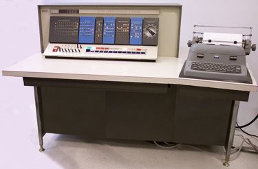
The "operating system" for the computer constituted the operator, who would use controls on the computer console, which consisted of a front panel and typewriter, to load programs from the available bulk storage media such as decks of punched cards or rolls of paper tape that were kept in cabinets nearby. Later, the model 1311 disc storage device attached to the computer enabled a reduction in the fetch and carry of card decks or paper tape rolls, and a simple "Monitor" operating system could be loaded to help in selecting what to load from disc.
A standard preliminary was to clear the computer memory of any previous user's detritus - being magnetic cores, the memory retained its last state even if the power had been switched off. This was effected by using the console facilities to load a simple computer program via typing its machine code at the console typewriter, running it, and stopping it. This was not challenging as only one instruction was needed such as 160001000000, loaded at address zero and following. This meant transmit field immediate (the 16: two digit op-codes) to address 00010 the immediate constant field having the value 00000 (five digit operand fields, the second being from address 11 back to 7), decrementing source and destination addresses until such time as a digit with a "flag" was copied. This was the normal machine code means of copying a constant of up to five digits. The digit string was addressed at its low-order end and extended through lower addresses until a digit with a flag marked its end. But for this instruction, no flag would ever be found because the source digits had shortly before been overwritten by digits lacking a flag. Thus the operation would roll around memory (even overwriting itself) filling it with all zeroes until the operator grew tired of watching the roiling of the indicator lights and pressed the Instant Stop - Single Cycle Execute button. Each 20,000 digit module of memory took just under one second to clear. On the 1620 II this instruction would NOT work (due to certain optimizations in the implementation). Instead there was a button on the console called Modify which when pressed together with the Check Reset button, when the computer was in Manual mode, would set the computer in a mode that would clear all of memory in a tenth of one second regardless of how much memory you had; when you pressed Start. It also stopped automatically when memory was cleared, instead of requiring the operator to stop it.
Other than typing machine code at the console, a program could be loaded via either the paper tape reader, the card reader, or any disk drive. Loading from either tape or disk required first typing a "bootstrap" routine on the console typewriter.
The card reader made things easier because it had a special Load button to signify that the first card was to be read into the computer's memory (starting at address 00000) and executed (as opposed to just starting the card reader, which then awaits commands from the computer to read cards) - this is the "bootstrap" process that gets into the computer just enough code to read in the rest of the code (from the card reader, or disc, or...) that constitutes the loader that will read in and execute the desired program.
Programs were prepared ahead of time, offline, on paper tape or punched cards. But usually the programmers were allowed to run the programs personally, hands-on, instead of submitting them to operators as was the case with mainframe computers at that time. And the console typewriter allowed entering data and getting output in an interactive fashion, instead of just getting the normal printed output from a blind batch run on a pre-packaged data set. As well, there were four program switches on the console whose state a running program could test and so have its behavior directed by its user. The computer operator could also stop a running program (or it may come to a deliberately programmed stop) then investigate or modify the contents of memory: being decimal-based, this was quite easy; even floating-point numbers could be read at a glance. Execution could then be resumed, from any desired point. Aside from debugging, scientific programming is typically exploratory, by contrast to commercial data processing where the same work is repeated on a regular schedule.
Console
For details of console lights, switches, and procedures see the respective articles on the IBM 1620 Model I or IBM 1620 Model II.The most important items on the 1620s console were a pair of buttons labeled Insert & Release, and the electric typewriter.
The typewriter is used for operator input/output, both as the main console control of the computer and for program controlled input/output. Later models of the typewriter had a special key marked R-S that combined the functions of the console Release & Start buttons (this would be considered equivalent to an Enter key on a modern keyboard). Note: several keys on the typewriter did not generate input characters, these included Tab and Return (the 1620s alphameric and numeric BCD character sets lacked character codes for these keys).
The next most important items on the 1620s console were the buttons labeled Start, Stop-SIE, and Instant Stop-SCE.
For program debugging there were the buttons labeled Save & Display MAR.
When a Branch Back instruction was executed in Save mode, it copied the saved value back to the program counter (instead of copying the return address register as it normally did) and deactivated Save mode.
This was used during debugging to remember where the program had been stopped to allow it to be resumed after the debugging instructions that the operator had typed on the typewriter had finished. Note: the MARS register used to save the program counter in was also used by the Multiply instruction, so this instruction and the Save mode were incompatible! However, there was no need to use multiply in debugging code, so this was not considered to be a problem.
Paper Tape reader/punch
The 1621 Tape reader and 1624 Tape punch controls.
Card reader/punch
The 1622 Card reader/punch controls were divided into three groups: 3 punch control rocker switches, 6 buttons, and 2 reader control rocker switches.
Punch Rocker switches:
Buttons:
Reader Rocker switches:
Disk drives
The 1311 Disk drive controls.
General
The FORTRAN II compiler and SPS assembler were somewhat cumbersome to use by modern standards, however, with repetition, the procedure soon became automatic and you no longer thought about the details involved.
GOTRAN was much simpler to use, as it directly produced an executable in memory. However it was not a complete FORTRAN implementation.
To improve this various third-party FORTRAN compilers were developed. One of these was developed by Bob Richardson, a programmer at Rice University, the FLAG (FORTRAN Load-and-Go) compiler. Once the FLAG deck had been loaded, all that was needed was to load the source deck to get directly to the output deck; FLAG stayed in memory, so it was immediately ready to accept the next source deck. This was particularly convenient for dealing with many small jobs. For instance, at Auckland University a batch job processor for student assignments (typically, many small programs not requiring much memory) chugged through a class lot rather faster than the later IBM 1130 did with its disk-based system. The compiler remained in memory, and the student's program had its chance in the remaining memory to succeed or fail, though a bad failure might disrupt the resident compiler.
Later, disk storage devices were introduced, removing the need for working storage on card decks. The various decks of cards constituting the compiler and loader no longer need be fetched from their cabinets but could be stored on disk and loaded under the control of a simple disk-based operating system: a lot of activity becomes less visible, but still goes on.
Since the punch side of the card reader-punch didn't edge-print the characters across the top of the cards, one had to take any output decks over to a separate machine, typically an IBM 557 Alphabetic Interpreter, that read each card and printed its contents along the top. Listings were usually generated by punching a listing deck and using an IBM 407 accounting machine to print the deck.
Hardware implementation
Most of the logic circuitry of the 1620 was a type of resistor-transistor logic (RTL) using "drift" transistors (a type of transistor invented by Herbert Kroemer in 1953) for their speed, that IBM referred to as Saturated Drift Transistor Resistor Logic (SDTRL). Other IBM circuit types used were referred to as: Alloy (some logic, but mostly various non-logic functions, named for the kind of transistors used), CTRL (another type of RTL, but slower than SDTRL), CTDL (a type of diode-transistor logic (DTL)), and DL (another type of RTL, named for the kind of transistor used, "drift" transistors). Typical logic levels of all these circuits (S Level) were high: 0 V to -0.5 V, low: -6 V to -12 V. Transmission line logic levels of SDTRL circuits (C Level) were high: 1 V, low: -1 V. Relay circuits used either of two logic levels (T Level) high: 51 V to 46 V, low: 16 V to 0 V or (W Level) high: 24 V, low: 0 V.
These circuits were constructed of individual discrete components mounted on single sided paper-epoxy printed circuit boards 2.5 by 4.5 inches (64 by 114 millimetres) with a 16-pin gold plated edge connector, that IBM referred to as SMS cards (Standard Modular System). The amount of logic on one card was similar to that in one 7400 series SSI or simpler MSI package (e.g., 3 to 5 logic gates or a couple of flip-flops).
These boards were inserted into sockets mounted in door-like racks which IBM referred to as gates. The machine had the following "gates" in its basic configuration:
There were two different types of core memory used in the 1620:
The address decoding logic of the Main memory also used two planes of 100 pulse transformer cores per module to generate the X-Y Line half-current pulses.
There were two models of the 1620, each having totally different hardware implementations:
A computer for the "small scientific market"
In 1958 IBM assembled a team at the Poughkeepsie, New York development laboratory to study the "small scientific market". Initially the team consisted of Wayne Winger (Manager), Robert C. Jackson, and William H. Rhodes.
Requirements and design
The competing computers in this market were the Librascope LGP-30 and the Bendix G-15; both were drum memory machines. IBM's smallest computer at the time was the popular IBM 650, a fixed word length decimal machine that also used drum memory. All three used vacuum tubes. It was concluded that IBM could offer nothing really new in that area. To compete effectively would require use of technologies that IBM had developed for larger computers, yet the machine would have to be produced at the least possible cost.
To meet this objective, the team set the following requirements:
The internal code name CADET was selected for the machine. One of the developers says that this stood for "Computer with ADvanced Economic Technology", however others recall it as simply being one half of "SPACE - CADET", where SPACE was the internal code name of the IBM 1401 machine, also then under development.
The prototype
The team expanded with the addition of Anne Deckman, Kelly B. Day, William Florac, and James Brenza. They completed the CADET prototype in the spring of 1959.
Meanwhile, the San Jose, California facility was working on a proposal of its own. IBM could only build one of the two and the Poughkeepsie proposal won because "the San Jose version is top of the line and not expandable, while your proposal has all kinds of expansion capability - never offer a machine that cannot be expanded".
Management was not entirely convinced that core memory could be made to work in small machines, so Gerry Ottaway was loaned to the team to design a drum memory as a backup. During acceptance testing by the Product Test Lab, repeated core memory failures were encountered and it looked likely that management's predictions would come true. However, at the last minute it was found that the muffin fan used to blow hot air through the core stack was malfunctioning, causing the core to pick up noise pulses and fail to read correctly. After the fan problem was fixed, there were no further problems with the core memory and the drum memory design effort was discontinued as unnecessary.
Transferred to San Jose for production
Following announcement of the IBM 1620 on October 21, 1959, due to an internal reorganization of IBM, it was decided to transfer the computer from the Data Processing Division at Poughkeepsie (large scale mainframe computers only) to the General Products Division at San Jose (small computers and support products only) for manufacturing.
Following transfer to San Jose, someone there jokingly suggested that the code name CADET actually stood for "Can't Add, Doesn't Even Try", referring to the use of addition tables in memory rather than dedicated addition circuitry. This stuck and became very well known among the user community.
Implementation "levels"
Related peripheral units
Available peripherals were:
Notable Uses
An IBM 1620 model II was used by Vearl N. Huff, NASA Headquarters (FOB 10B, Washington DC) to program a three-dimensional simulation in Fortran of the tethered Gemini capsule - Agena rocket module two-body problem at a time when it was not completely understood if it was safe to tether two objects together in space due to possible elastic tether induced collisions. The same computer was also used to simulate the orbits of the Gemini flights, producing printer-art charts of each orbit. These simulation were run over-night and the data examined the next day.
In 1964 at the Australian National University, Martin Ward used an IBM 1620 model I to calculate the order of the Janko group J1.
In 1966 the ITU produced an explanatory film on a 1963 system for typesetting by computer at the Washington Evening Star, using an IBM 1620 and a Linofilm phototypesetter.
Use in film and television
A radio program was developed by DJ Rege Cordic for KDKA Pittsburgh, based on a baseball game simulator developed by John Burgeson of IBM and his brother, Paul, then an ensign in the U.S. Navy. This program was used in numerous demonstration events in the years 1960 to 1963 as an example of the power of computers to perform simulation exercises. The fictional computer Colossus of Colossus: The Forbin Project used about a dozen scrapped 1620 front panels purchased on the surplus market, in various orientations. A similar arrangement was used in a late episode of The Man from U.N.C.L.E. to portray a THRUSH supercomputer.