
Design CISC Encoding Variable | Introduced 1959 Type Memory-Memory | |
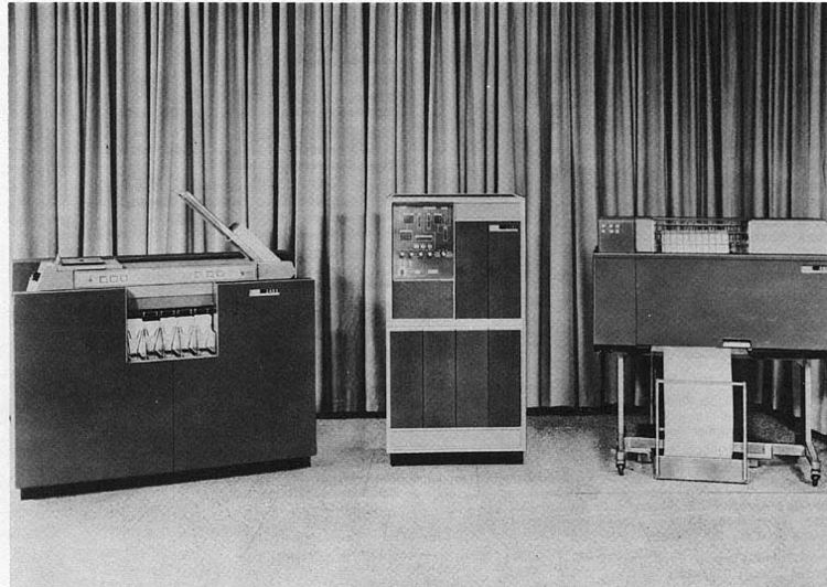 | ||
The IBM 1401 is a variable wordlength decimal computer that was announced by IBM on October 5, 1959. The first member of the highly successful IBM 1400 series, it was aimed at replacing unit record equipment for processing data stored on punched cards and at providing peripheral services for larger computers. Over 12,000 units were produced and many were leased or resold after they were replaced with newer technology. The 1401 was withdrawn on February 8, 1971.
Contents
History
From the announcement:
The all-transistorized IBM 1401 Data Processing System places the features found in electronic data processing systems at the disposal of smaller businesses, previously limited to the use of conventional punched card equipment. These features include: high speed card punching and reading, magnetic tape input and output, high speed printing, stored program, and arithmetic and logical ability.'
Monthly rental for 1401 configurations started at US$2,500 (worth about $20,539 today).
"IBM was pleasantly surprised (perhaps shocked) to receive 5,200 orders in just the first five weeks – more than predicted for the entire life of the machine!" By late 1961, the 2000 installed in the USA were about one quarter of all electronic stored-program computers by all manufacturers. The number of installed 1401s peaked above 10,000 in the mid-1960s. "In all, by the mid-1960s nearly half of all computer systems in the world were 1401-type systems." The system was marketed until February 1971.
Commonly used by small businesses as their primary data processing machines, the 1401 was also frequently used as an off-line peripheral controller for mainframe computers. In such installations, with an IBM 7090 for example, the mainframe computers used only magnetic tape for input-output. It was the 1401 that transferred input data from slow peripherals (such as the IBM 1402 Card Read-Punch) to tape, and transferred output data from tape to the card punch, the IBM 1403 Printer, or other peripherals. This allowed the mainframe's throughput to not be limited by the speed of a card reader or printer. (For more information, see Spooling.)
Elements within IBM, notably John Haanstra, an executive in charge of 1401 deployment, supported its continuation in larger models for evolving needs (e.g., the IBM 1410) but the 1964 decision at the top to focus resources on the System/360 ended these efforts rather suddenly. Then, faced with the competitive threat of the Honeywell 200 and the 360's incompatibility with the 1401 design, IBM pioneered the use of microcode emulation, in the form of ROM, so that some System/360 models could run 1401 programs.
During the 1970s, IBM installed many 1401s in India and Pakistan where they were in use well into the 1980s. Some of today's Indian and Pakistani software entrepreneurs started on these 1401s. The first computer in Pakistan, for example, was a 1401 installed at Pakistan International Airlines.
Two 1401 systems have been restored to operating order at the Computer History Museum in Mountain View, California, complete with a raised floor typical of the mainframe era (and modern data centers), used to hide cabling and distribute cooled air.
Architecture
Each alphanumeric character in the 1401 was encoded by six bits, called B,A,8,4,2,1. The B,A bits were called zone bits and the 8,4,2,1 bits were called numeric bits, terms taken from the IBM 80 column punched card.
IBM called the 1401's character code BCD, even though that term describes only the decimal digit encoding. The 1401's alphanumeric collating sequence was compatible with the punched card collating sequence.
Associated with each memory location were two other bits, called C for odd parity check and M for word mark.
Each memory location then, had the following bits:
C B A 8 4 2 1 M
The 1401 was available in six memory configurations: 1400, 2000, 4000, 8000, 12000, or 16000 characters. Each character was addressable, addresses ranging from 0 through 15999. A very small number of 1401s were expanded to 32,000 characters by special request.
Some operations used specific memory locations (those locations were not reserved and could be used for other purposes). Read a card stored the 80 columns of data from a card into memory locations 001-080. Index registers 1, 2 and 3 were in memory locations 087-089, 092-094 and 097-099 respectively. Punch a card punched the contents of memory locations 101-180 into a card. Write a line printed the contents of memory locations 201-332.
The 1401's instruction format was
Opcode with [A-or-I-or-unit-address [B-address]] [modifier] word markOpcodes were one character. Memory addresses ("I" a branch target, "A" and "B" data) and unit address were three characters. The opcode modifier was one character. Instruction length was then 1, 2, 4, 5, 7, or 8 characters. Most instructions had to be followed by a word mark (a requirement commonly met by the word mark with the opcode of the next instruction).
See Character and op codes for a list of operations.
A three character memory address in an instruction was an encoding of a five digit memory address. The three low order digits of the five digit address, 000 to 999, were specified by the numeric bits of the three characters. The zone bits of the high-order character specified an increment as follows: A 1000, B 2000, B and A together 3000, giving an addressability of 4,000 memory locations. The zone bits of the low-order character specified increments of 4000, 8000, or 12000, to address 16,000 memory locations (with an IBM 1406 Storage Unit). For example, the three character address "I99" was a reference to memory location 3000 + 999, or 3999.
The zone bits of the middle character of a three character memory address could specify one of three index registers, one of many optional features.
Operands referenced by the A-address and B-address were: a single memory location, a variable length field, or a variable length record. Variable length fields were addressed at their low-order (highest-addressed) position, their length defined by a word mark set at their high-order (lowest-addressed) position. When an operation such as addition was performed, the processor began at the low-order position of the two fields and worked its way to the high-order, just as a person would when adding with pencil and paper.
The only limit on the length of such fields was the available memory. Instructions applicable to variable length fields included: Add, Subtract, Multiply, Divide, Compare, Move Characters to A or B Word Mark, Move Characters and Edit. One or more adjacent variable length fields could make up a variable length record. A variable length record was addressed at its high-order position, its length defined by a group-mark character with a word mark or a record-mark character in its low-order position. The instruction Move Characters Record or Group Mark could be used to assemble a block of records. A variable length record, or block of records, to be written to magnetic tape was addressed at its high-order position, its length defined by a group-mark character with a word mark immediately following its low-order position.
A sequence of operations on adjacent fields could be "chained", using the addresses left in the address registers by the previous operation. For example, addition of adjacent data fields might be coded as "A 700,850", "A 695,845", "A 690,840". With chaining, this could be coded as "A 700,850", "A", "A" - omitting data address from the 2nd and 3rd instructions.
Booting and sample program
When the LOAD button on the 1402 Card Read-Punch was pressed, a card was read into memory locations 001-080, a word mark was set in location 001, the word marks in locations 002-080 were cleared, and execution started with the instruction at location 001. That was always the dyadic Set Word Mark (it was the only instruction not requiring a following word mark) to set word marks for the two following instructions. Execution of instructions in the card deck continued, loading the program into memory, setting word marks, and then branching to the program's start address.
One-card programs could be written for various tasks. Commonly available were a one-card program to print the deck of cards following it, and another to duplicate a deck to the card punch. From Tom Van Vleck's web site here is a one-card program which will print "HELLO WORLD". Pressing LOAD (above) begins execution at location 001 (the first ",").
,008015,022029,036043,050054,055062,063065,069080/333/M0792502F1.065HELLO WORLDThe program is:
Hardware implementation
Most of the logic circuitry of the 1401 was a type of diode-transistor logic (DTL), that IBM referred to as CTDL (Complemented Transistor Diode Logic). Other IBM circuit types used were referred to as: Alloy (some logic, but mostly various non-logic functions, named for the germanium-alloy transistors used), CTRL (Complemented Transistor Resistor Logic, a type of resistor-transistor logic (RTL)). Later upgrades (e.g., the TAU-9 tape interface) used a faster type of DTL using "drift" transistors (a type of transistor invented by Herbert Kroemer in 1953) for their speed, that IBM referred to as SDTDL (Saturated Drift Transistor Diode Logic). Typical logic levels of these circuits were (S & U Level) high: 0 V to -0.5V, low: -6 V to -12 V; (T Level) high: 6 V to 1 V, low: -5.5 V to -6 V.
These circuits were constructed of discrete components (resistors, capacitors, transistors) mounted on single sided paper-epoxy printed circuit boards either 2.5 by 4.5 inches (64 by 114 mm) with a 16-pin gold plated edge connector (single wide) or 5.375 by 4.5 inches (136.5 by 114.3 mm) with two 16-pin gold plated edge connectors (double wide), that IBM referred to as SMS cards (Standard Modular System). The amount of logic on one card was similar to that in one 7400 series SSI or simpler MSI package (e.g., 3 to 5 logic gates or a couple of flip-flops on a single wide card up to about 20 logic gates or 4 flip-flops on a double wide card).
The SMS cards were inserted in sockets on hinged swing out racks, that IBM referred to as gates.
Like most machines of the day, the 1401 used magnetic-core memory. The cores were about 1 mm in diameter and used a four-wire arrangement (x, y, sense, and inhibit). The memory was arranged in planes of 4000 cores each, each core storing one bit. A stack of eight such planes stored the six data bits, word mark bit, and parity bit for 4000 memory locations. Together with eight additional planes with fewer cores on them for additional storage functions, this made up a 4000-character memory module. One such module could be housed within the 1401's primary enclosure. Systems were commonly available with two, three, or four such modules. The additional modules were contained in an add-on box, the 1406 Core Memory Unit, which was about two feet square and three high.
Operands in memory were accessed serially, one memory location at a time, and the 1401 could read or write one memory location within its basic cycle time of 11.5 microseconds. All instruction timings were cited in multiples of this cycle time.
Software
IBM software for the 1401 included:
For the IBM Catalog of 1401 software, see IBM 1400 series.
Character and op codes
The 1401's operation codes were single characters. In many cases, particularly for the more common instructions, the character chosen was mnemonic for the operation: A for add, B for branch, S for subtract, etc.
The table is in Character Collating Sequence.
Note: If Word mark bit is set, then the C bit will be opposite of shown. The C bit was determined and checked automatically by the machine - normally it was of no concern to the programmers. The only way the C bit could be entered was by manually using the switches on the Auxiliary Console. A programmer might use these switches to make quick patches while debugging.Two of the instructions, Branch on Indicator (B) and Select Stacker (K), use a "modifier" operand.
1401 culture
In October 2006, Icelandic avant-garde musician Jóhann Jóhannsson released the album IBM 1401, A User's Manual through music publisher 4AD. The concept is based upon work done in 1964 by his father, Jóhann Gunnarsson, chief maintenance engineer of one of the country's first computers, and Elías Daviðsson, one of the first programmers in the country. The album was originally written for a string quartet, organ and electronics and to accompany a dance piece by long-standing collaborator friend, Erna Ómarsdóttir. For the album recording, Jóhann has rewritten it for a sixty-piece string orchestra, adding a new final movement and incorporating electronics and vintage reel-to-reel recordings of a singing 1401 found in his father's attic.
More well-known were various demo programs to play music on transistor radios placed on the CPU and computer "art", mostly kitschy pictures printed using Xs and 0s on chain printers.