
 | ||
The IBM 1620 Model I was the original implementation of the IBM 1620 scientific computer, introduced in 1959.
Contents
This unit (commonly called "1620" until the Model II was introduced) was produced as inexpensively as IBM could make it, in order to keep the price low. One industry magazine (Datamation) mentioned that the 1620 was the first IBM computer for which the basic system could be leased for a monthly rate that was numerically smaller than its model number.
It did not even have conventional ALU hardware: all arithmetic was done by table lookup in core memory. Addition and Subtraction used a 100-digit table (@ address 00300..00399). Multiplication used a 200-digit table (@ address 00100..00299). In the basic machine division used software subroutines, but optional divide hardware could be installed using a repeated subtraction algorithm. Floating point arithmetic instructions were an available option (if the divide option was installed).
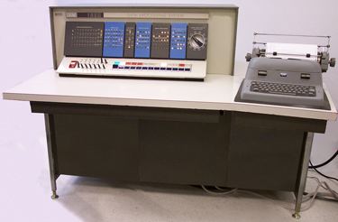
The console typewriter was a modified Model B1, which typed at only 10 characters per second. (This typewriter had a very 'nasty' habit of breaking off its "0" hammer and throwing it across the room in the middle of a long core dump. )
The first 20,000 decimal digits of Magnetic-core memory were internal to the CPU itself (which reduced the floor space requirements of the basic system). Expansion to either 40,000 or 60,000 decimal digits required the addition of an IBM 1623 Memory unit. The memory cycle time was 20μs ( that is, the memory speed was 50kHz = 1/20th of a MHz). A Memory Address Register Storage (MARS) Core memory read, clear, or write operation took 2 μs and each write operation was automatically (but not necessarily immediately) preceded by a read or clear operation of the same "register(s)" during the 20 μs memory cycle.
The central processor clock speed was 1 MHz, which was divided by 20 by a 10 position ring counter to provide the system timing/control signals.
Instructions took 8 memory cycles (160 μs) to fetch and a variable number of memory cycles to execute. Indirect addressing added 4 memory cycles (80 μs) for each level of indirection.
Non-decimal arithmetic
It is commonly believed that since this model used lookup tables in memory that simply changing the contents of these tables allowed the programmer to do arithmetic in any base from 2 to 10. This is only partially true as the hardware included a ten's complementer for subtraction (and addition of oppositely signed numbers). Therefore, only addition of unsigned numbers could be correctly performed in bases 5 to 9. To do fully signed addition and subtraction in bases 2 to 4 required detailed understanding of the hardware to create a "folded" addition table that would fake out the complementer and carry logic. Also the addition table would have to be reloaded for normal base 10 operation every time address calculations were required in the program, then reloaded again for the alternate base. This made the "trick" somewhat less than useful for any practical application.
Upper console
Lower console
Typewriter
The typewriter was a standard IBM office electric typewriter, interfaced by a set of relays. It could type 10 characters per second, and there were a set of instructions that wrote to the typewriter, or read from it. The general RN (read numeric) and WN (write numeric) instructions had assembly language mnemonics that supplied the "device" code in the second address field, and the control code in the low-order digit of the second address field.
To simplify input and output, there were two instructions
In later models of the 1620, the original IBM typewriter was replaced with an IBM Selectric typewriter, which could type nearly 15 characters per second.
The standard "output" mechanism for a program was to punch cards, which was faster than using the typewriter. These punched cards were then fed through an IBM 407 mechanical calculator which could be programmed to print two cards, thus being able to use the additional print columns available on the 407. All output was synchronous, and the processor paused while the I/O device produced the output, so the typewriter output could completely dominate program running time.
In later models, a 1443 line printer could be attached, which could print faster than the data could be put out on punch cards. The line printer could print 120 or 144 columns. The character width was fixed, so it was the paper size that changed; the printer printed 10 characters to the inch, so a printer could print a maximum of 12 inches or 14.4 inches of text. In addition, the printer had a buffer, so the I/O delay for the processor was reduced. However, the print instruction would block if the line had not completed.