
 | ||
An electromagnet is a type of magnet in which the magnetic field is produced by an electric current. The magnetic field disappears when the current is turned off. Electromagnets usually consist of insulated wire wound into a coil. A current through the wire creates a magnetic field which is concentrated in the hole in the center of the coil. The wire turns are often wound around a magnetic core made from a ferromagnetic or ferrimagnetic material such as iron; the magnetic core concentrates the magnetic flux and makes a more powerful magnet.
Contents
- History
- Uses of electromagnets
- Simple solenoid
- Physics
- Amperes law
- Magnetic core
- Magnetic circuit the constant B field approximation
- Magnetic field created by a current
- Force exerted by magnetic field
- Closed magnetic circuit
- Force between electromagnets
- Side effects
- Ohmic heating
- Inductive voltage spikes
- Lorentz forces
- Core losses
- Superconducting electromagnets
- Bitter electromagnets
- Exploding electromagnets
- References
The main advantage of an electromagnet over a permanent magnet is that the magnetic field can be quickly changed by controlling the amount of electric current in the winding. However, unlike a permanent magnet that needs no power, an electromagnet requires a continuous supply of current to maintain the magnetic field.
Electromagnets are widely used as components of other electrical devices, such as motors, generators, relays, loudspeakers, hard disks, MRI machines, scientific instruments, and magnetic separation equipment. Electromagnets are also employed in industry for picking up and moving heavy iron objects such as scrap iron and steel.
History
Danish scientist Hans Christian Ørsted discovered in 1820 that electric currents create magnetic fields. British scientist William Sturgeon invented the electromagnet in 1824. His first electromagnet was a horseshoe-shaped piece of iron that was wrapped with about 18 turns of bare copper wire (insulated wire didn't exist yet). The iron was varnished to insulate it from the windings. When a current was passed through the coil, the iron became magnetized and attracted other pieces of iron; when the current was stopped, it lost magnetization. Sturgeon displayed its power by showing that although it only weighed seven ounces (roughly 200 grams), it could lift nine pounds (roughly 4 kilos) when the current of a single-cell battery was applied. However, Sturgeon's magnets were weak because the uninsulated wire he used could only be wrapped in a single spaced out layer around the core, limiting the number of turns.
Beginning in 1830, US scientist Joseph Henry systematically improved and popularized the electromagnet. By using wire insulated by silk thread, and inspired by Schweigger's use of multiple turns of wire to make a galvanometer, he was able to wind multiple layers of wire on cores, creating powerful magnets with thousands of turns of wire, including one that could support 2,063 lb (936 kg). The first major use for electromagnets was in telegraph sounders.
The magnetic domain theory of how ferromagnetic cores work was first proposed in 1906 by French physicist Pierre-Ernest Weiss, and the detailed modern quantum mechanical theory of ferromagnetism was worked out in the 1920s by Werner Heisenberg, Lev Landau, Felix Bloch and others.
Uses of electromagnets
A portative electromagnet is one designed to just hold material in place; an example is a lifting magnet. A tractive electromagnet applies a force and moves something.
Electromagnets are very widely used in electric and electromechanical devices, including:
Simple solenoid
A common tractive electromagnet is a uniformly-wound solenoid and plunger. The solenoid is a coil of wire, and the plunger is made of a material such as soft iron. Applying a current to the solenoid applies a force to the plunger and may make it move. The plunger stops moving when the forces upon it are balanced. For example, the forces are balanced when the plunger is centered in the solenoid.
The maximum uniform pull happens when one end of the plunger is at the middle of the solenoid. An approximation for the force F is
where C is a proportionality constant, A is the cross-sectional area of the plunger, n is the number of turns in the solenoid, I is the current through the solenoid wire, and l is the length of the solenoid. For units using inches, pounds force, and amperes with long, slender, solenoids, the value of C is around 0.009 to 0.010 psi (maximum pull pounds per square inch of plunger cross-sectional area). For example, a 12-inch long coil (l=12 in) with a long plunger of 1-square inch cross section (A=1 in2) and 11,200 ampere-turns (n I=11,200 Aturn) had a maximum pull of 8.75 pounds (corresponding to C=0.0094 psi).
The maximum pull is increased when a magnetic stop is inserted into the solenoid. The stop becomes a magnet that will attract the plunger; it adds little to the solenoid pull when the plunger is far away but dramatically increases the pull when they are close. An approximation for the pull P is
Here la is the distance between the end of the stop and the end of the plunger. The additional constant C1 for units of inches, pounds, and amperes with slender solenoids is about 2660. The second term within the bracket represents the same force as the stop-less solenoid above; the first term represents the attraction between the stop and the plunger.
Some improvements can be made on the basic design. The ends of the stop and plunger are often conical. For example, the plunger may have a pointed end that fits into a matching recess in the stop. The shape makes the solenoid's pull more uniform as a function of separation. Another improvement is to add a magnetic return path around the outside of the solenoid (an "iron-clad solenoid"). The magnetic return path, just as the stop, has little impact until the air gap is small.
Physics
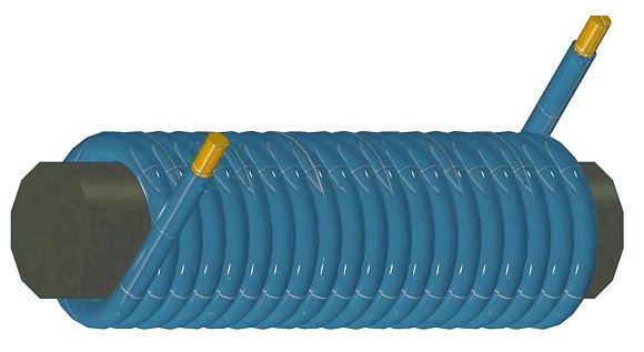
An electric current flowing in a wire creates a magnetic field around the wire, due to Ampere's law (see drawing below). To concentrate the magnetic field, in an electromagnet the wire is wound into a coil with many turns of wire lying side by side. The magnetic field of all the turns of wire passes through the center of the coil, creating a strong magnetic field there. A coil forming the shape of a straight tube (a helix) is called a solenoid.
The direction of the magnetic field through a coil of wire can be found from a form of the right-hand rule. If the fingers of the right hand are curled around the coil in the direction of current flow (conventional current, flow of positive charge) through the windings, the thumb points in the direction of the field inside the coil. The side of the magnet that the field lines emerge from is defined to be the north pole.
Much stronger magnetic fields can be produced if a "magnetic core" of a soft ferromagnetic (or ferrimagnetic) material, such as iron, is placed inside the coil. A core can increase the magnetic field to thousands of times the strength of the field of the coil alone, due to the high magnetic permeability μ of the material. This is called a ferromagnetic-core or iron-core electromagnet. However, not all electromagnets use cores, and the very strongest electromagnets, such as superconducting and the very high current electromagnets, cannot use them due to saturation.
Ampere's law
For definitions of the variables below, see box at end of article.
The magnetic field of electromagnets in the general case is given by Ampere's Law:
which says that the integral of the magnetizing field H around any closed loop of the field is equal to the sum of the current flowing through the loop. Another equation used, that gives the magnetic field due to each small segment of current, is the Biot–Savart law. Computing the magnetic field and force exerted by ferromagnetic materials is difficult for two reasons. First, because the strength of the field varies from point to point in a complicated way, particularly outside the core and in air gaps, where fringing fields and leakage flux must be considered. Second, because the magnetic field B and force are nonlinear functions of the current, depending on the nonlinear relation between B and H for the particular core material used. For precise calculations, computer programs that can produce a model of the magnetic field using the finite element method are employed.
Magnetic core
The material of a magnetic core (often made of iron or steel) is composed of small regions called magnetic domains that act like tiny magnets (see ferromagnetism). Before the current in the electromagnet is turned on, the domains in the iron core point in random directions, so their tiny magnetic fields cancel each other out, and the iron has no large scale magnetic field. When a current is passed through the wire wrapped around the iron, its magnetic field penetrates the iron, and causes the domains to turn, aligning parallel to the magnetic field, so their tiny magnetic fields add to the wire's field, creating a large magnetic field that extends into the space around the magnet. The effect of the core is to concentrate the field, and the magnetic field passes through the core more easily than it would pass through air.
The larger the current passed through the wire coil, the more the domains align, and the stronger the magnetic field is. Finally all the domains are lined up, and further increases in current only cause slight increases in the magnetic field: this phenomenon is called saturation.
When the current in the coil is turned off, in the magnetically soft materials that are nearly always used as cores, most of the domains lose alignment and return to a random state and the field disappears. However some of the alignment persists, because the domains have difficulty turning their direction of magnetization, leaving the core a weak permanent magnet. This phenomenon is called hysteresis and the remaining magnetic field is called remanent magnetism. The residual magnetization of the core can be removed by degaussing. In alternating current electromagnets, such as are used in motors, the core's magnetisation is constantly reversed, and the remanence contributes to the motor's losses.
Magnetic circuit – the constant B field approximation
In many practical applications of electromagnets, such as motors, generators, transformers, lifting magnets, and loudspeakers, the iron core is in the form of a loop or magnetic circuit, possibly broken by a few narrow air gaps. This is because the magnetic field lines are in the form of closed loops. Iron presents much less "resistance" (reluctance) to the magnetic field than air, so a stronger field can be obtained if most of the magnetic field's path is within the core.
Since most of the magnetic field is confined within the outlines of the core loop, this allows a simplification of the mathematical analysis. See the drawing at right. A common simplifying assumption satisfied by many electromagnets, which will be used in this section, is that the magnetic field strength B is constant around the magnetic circuit (within the core and air gaps) and zero outside it. Most of the magnetic field will be concentrated in the core material (C). Within the core the magnetic field (B) will be approximately uniform across any cross section, so if in addition the core has roughly constant area throughout its length, the field in the core will be constant. This just leaves the air gaps (G), if any, between core sections. In the gaps the magnetic field lines are no longer confined by the core, so they 'bulge' out beyond the outlines of the core before curving back to enter the next piece of core material, reducing the field strength in the gap. The bulges (BF) are called fringing fields. However, as long as the length of the gap is smaller than the cross section dimensions of the core, the field in the gap will be approximately the same as in the core. In addition, some of the magnetic field lines (BL) will take 'short cuts' and not pass through the entire core circuit, and thus will not contribute to the force exerted by the magnet. This also includes field lines that encircle the wire windings but do not enter the core. This is called leakage flux. Therefore, the equations in this section are valid for electromagnets for which:
- the magnetic circuit is a single loop of core material, possibly broken by a few air gaps
- the core has roughly the same cross sectional area throughout its length.
- any air gaps between sections of core material are not large compared with the cross sectional dimensions of the core.
- there is negligible leakage flux
The main nonlinear feature of ferromagnetic materials is that the B field saturates at a certain value, which is around 1.6 to 2 teslas (T) for most high permeability core steels. The B field increases quickly with increasing current up to that value, but above that value the field levels off and becomes almost constant, regardless of how much current is sent through the windings. So the maximum strength of the magnetic field possible from an iron core electromagnet is limited to around 1.6 to 2 T.
Magnetic field created by a current
The magnetic field created by an electromagnet is proportional to both the number of turns in the winding, N, and the current in the wire, I, hence this product, NI, in ampere-turns, is given the name magnetomotive force. For an electromagnet with a single magnetic circuit, of which length Lcore of the magnetic field path is in the core material and length Lgap is in air gaps, Ampere's Law reduces to:
This is a nonlinear equation, because the permeability of the core, μ, varies with the magnetic field B. For an exact solution, the value of μ at the B value used must be obtained from the core material hysteresis curve. If B is unknown, the equation must be solved by numerical methods. However, if the magnetomotive force is well above saturation, so the core material is in saturation, the magnetic field will be approximately the saturation value Bsat for the material, and won't vary much with changes in NI. For a closed magnetic circuit (no air gap) most core materials saturate at a magnetomotive force of roughly 800 ampere-turns per meter of flux path.
For most core materials,
Force exerted by magnetic field
The force exerted by an electromagnet on a section of core material is:
The force equation can be derived from the energy stored in a magnetic field. Energy is force times distance. Rearranging terms yields the equation above.
The 1.6 T limit on the field mentioned above sets a limit on the maximum force per unit core area, or pressure, an iron-core electromagnet can exert; roughly:
In more intuitive units it's useful to remember that at 1T the magnetic pressure is approximately 4 atmospheres, or kg/cm2.
Given a core geometry, the B field needed for a given force can be calculated from (2); if it comes out to much more than 1.6 T, a larger core must be used.
Closed magnetic circuit
For a closed magnetic circuit (no air gap), such as would be found in an electromagnet lifting a piece of iron bridged across its poles, equation (1) becomes:
Substituting into (2), the force is:
It can be seen that to maximize the force, a core with a short flux path L and a wide cross sectional area A is preferred (this also applies to magnets with an air gap). To achieve this, in applications like lifting magnets (see photo above) and loudspeakers a flat cylindrical design is often used. The winding is wrapped around a short wide cylindrical core that forms one pole, and a thick metal housing that wraps around the outside of the windings forms the other part of the magnetic circuit, bringing the magnetic field to the front to form the other pole.
Force between electromagnets
The above methods are applicable to electromagnets with a magnetic circuit, and do not apply when a large part of the magnetic field path is outside the core. An example would be a magnet with a straight cylindrical core like the one shown at the top of this article. For electromagnets (or permanent magnets) with well defined 'poles' where the field lines emerge from the core, the force between two electromagnets can be found using the 'Gilbert model' which assumes the magnetic field is produced by fictitious 'magnetic charges' on the surface of the poles, with pole strength m and units of Ampere-turn meter. Magnetic pole strength of electromagnets can be found from:
The force between two poles is:
This model doesn't give the correct magnetic field inside the core, and thus gives incorrect results if the pole of one magnet gets too close to another magnet.
Side effects
There are several side effects which occur in electromagnets which must be provided for in their design. These generally become more significant in larger electromagnets.
Ohmic heating
The only power consumed in a DC electromagnet is due to the resistance of the windings, and is dissipated as heat. Some large electromagnets require cooling water circulating through pipes in the windings to carry off the waste heat.
Since the magnetic field is proportional to the product NI, the number of turns in the windings N and the current I can be chosen to minimize heat losses, as long as their product is constant. Since the power dissipation, P = I2R, increases with the square of the current but only increases approximately linearly with the number of windings, the power lost in the windings can be minimized by reducing I and increasing the number of turns N proportionally, or using thicker wire to reduce the resistance. For example, halving I and doubling N halves the power loss, as does doubling the area of the wire. In either case, increasing the amount of wire reduces the ohmic losses. For this reason, electromagnets often have a significant thickness of windings.
However, the limit to increasing N or lowering the resistance is that the windings take up more room between the magnet's core pieces. If the area available for the windings is filled up, more turns require going to a smaller diameter of wire, which has higher resistance, which cancels the advantage of using more turns. So in large magnets there is a minimum amount of heat loss that can't be reduced. This increases with the square of the magnetic flux B2.
Inductive voltage spikes
An electromagnet has significant inductance, and resists changes in the current through its windings. Any sudden changes in the winding current cause large voltage spikes across the windings. This is because when the current through the magnet is increased, such as when it is turned on, energy from the circuit must be stored in the magnetic field. When it is turned off the energy in the field is returned to the circuit.
If an ordinary switch is used to control the winding current, this can cause sparks at the terminals of the switch. This doesn't occur when the magnet is switched on, because the voltage is limited to the power supply voltage, but when it is switched off, the energy in the magnetic field is suddenly returned to the circuit, causing a large voltage spike and an arc across the switch contacts, which can damage them. With small electromagnets a capacitor is often used across the contacts, which reduces arcing by temporarily storing the current. More often a diode is used to prevent voltage spikes by providing a path for the current to recirculate through the winding until the energy is dissipated as heat. The diode is connected across the winding, oriented so it is reverse-biased during steady state operation and doesn't conduct. When the supply voltage is removed, the voltage spike forward-biases the diode and the reactive current continues to flow through the winding, through the diode and back into the winding. A diode used in this way is called a flyback diode.
Large electromagnets are usually powered by variable current electronic power supplies, controlled by a microprocessor, which prevent voltage spikes by accomplishing current changes slowly, in gentle ramps. It may take several minutes to energize or deenergize a large magnet.
Lorentz forces
In powerful electromagnets, the magnetic field exerts a force on each turn of the windings, due to the Lorentz force
The Lorentz forces increase with B2. In large electromagnets the windings must be firmly clamped in place, to prevent motion on power-up and power-down from causing metal fatigue in the windings. In the Bitter design, below, used in very high field research magnets, the windings are constructed as flat disks to resist the radial forces, and clamped in an axial direction to resist the axial ones.
Core losses
In alternating current (AC) electromagnets, used in transformers, inductors, and AC motors and generators, the magnetic field is constantly changing. This causes energy losses in their magnetic cores that are dissipated as heat in the core. The losses stem from two processes:
The energy loss per cycle of the AC current is constant for each of these processes, so the power loss increases linearly with frequency.
Superconducting electromagnets
When a magnetic field higher than the ferromagnetic limit of 1.6 T is needed, superconducting electromagnets can be used. Instead of using ferromagnetic materials, these use superconducting windings cooled with liquid helium, which conduct current without electrical resistance. These allow enormous currents to flow, which generate intense magnetic fields. Superconducting magnets are limited by the field strength at which the winding material ceases to be superconducting. Current designs are limited to 10–20 T, with the current (2009) record of 33.8 T. The necessary refrigeration equipment and cryostat make them much more expensive than ordinary electromagnets. However, in high power applications this can be offset by lower operating costs, since after startup no power is required for the windings, since no energy is lost to ohmic heating. They are used in particle accelerators and MRI machines.
Bitter electromagnets
Both iron-core and superconducting electromagnets have limits to the field they can produce. Therefore, the most powerful man-made magnetic fields have been generated by air-core nonsuperconducting electromagnets of a design invented by Francis Bitter in 1933, called Bitter electromagnets. Instead of wire windings, a Bitter magnet consists of a solenoid made of a stack of conducting disks, arranged so that the current moves in a helical path through them, with a hole through the center where the maximum field is created. This design has the mechanical strength to withstand the extreme Lorentz forces of the field, which increase with B2. The disks are pierced with holes through which cooling water passes to carry away the heat caused by the high current. The strongest continuous field achieved solely with a resistive magnet is 37.5 T as of 31 March 2014, produced by a Bitter electromagnet at the Radboud University High Field Magnet Laboratory in Nijmegen, Holland. The previous record was 35 T. The strongest continuous magnetic field overall, 45 T, was achieved in June 2000 with a hybrid device consisting of a Bitter magnet inside a superconducting magnet.
Exploding electromagnets
The factor limiting the strength of electromagnets is the inability to dissipate the enormous waste heat, so more powerful fields, up to 100 T, have been obtained from resistive magnets by sending brief pulses of high current through them; the inactive period after each pulse allows the heat produced during the pulse to be removed, before the next pulse. The most powerful manmade magnetic fields have been created by using explosives to compress the magnetic field inside an electromagnet as it is pulsed, using explosively pumped flux compression generators. The implosion compresses the magnetic field to values of around 1000 T for a few microseconds. While this method may seem very destructive there are methods to control the blast so that neither the experiment nor the magnetic structure are harmed, by redirecting the brunt of the force radially outwards. These devices are known as destructive pulsed electromagnets. They are used in physics and materials science research to study the properties of materials at high magnetic fields.