
 | ||
The electrical resistance of an electrical conductor is a measure of the difficulty to pass an electric current through that conductor. The inverse quantity is electrical conductance, and is the ease with which an electric current passes. Electrical resistance shares some conceptual parallels with the notion of mechanical friction. The SI unit of electrical resistance is the ohm (Ω), while electrical conductance is measured in siemens (S).
Contents
- Introduction
- Conductors and resistors
- Ohms law
- Relation to resistivity and conductivity
- What determines resistivity
- Measuring resistance
- Static and differential resistance
- Impedance and admittance
- Frequency dependence of resistance
- Energy dissipation and Joule heating
- Temperature dependence
- Strain dependence
- Light illumination dependence
- Superconductivity
- References
An object of uniform cross section has a resistance proportional to its resistivity and length and inversely proportional to its cross-sectional area. All materials show some resistance, except for superconductors, which have a resistance of zero.
The resistance (R) of an object is defined as the ratio of voltage across it (V) to current through it (I), while the conductance (G) is the inverse:
For a wide variety of materials and conditions, V and I are directly proportional to each other, and therefore R and G are constant (although they can depend on other factors like temperature or strain). This proportionality is called Ohm's law, and materials that satisfy it are called ohmic materials.
In other cases, such as a diode or battery, V and I are not directly proportional. The ratio V/I is sometimes still useful, and is referred to as a "chordal resistance" or "static resistance", since it corresponds to the inverse slope of a chord between the origin and an I–V curve. In other situations, the derivative
Introduction
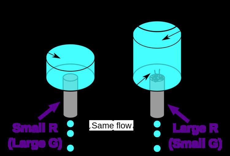
In the hydraulic analogy, current flowing through a wire (or resistor) is like water flowing through a pipe, and the voltage drop across the wire is like the pressure drop that pushes water through the pipe. Conductance is proportional to how much flow occurs for a given pressure, and resistance is proportional to how much pressure is required to achieve a given flow. (Conductance and resistance are reciprocals.)
The voltage drop (i.e., difference between voltages on one side of the resistor and the other), not the voltage itself, provides the driving force pushing current through a resistor. In hydraulics, it is similar: The pressure difference between two sides of a pipe, not the pressure itself, determines the flow through it. For example, there may be a large water pressure above the pipe, which tries to push water down through the pipe. But there may be an equally large water pressure below the pipe, which tries to push water back up through the pipe. If these pressures are equal, no water flows. (In the image at right, the water pressure below the pipe is zero.)
The resistance and conductance of a wire, resistor, or other element is mostly determined by two properties:
Geometry is important because it is more difficult to push water through a long, narrow pipe than a wide, short pipe. In the same way, a long, thin copper wire has higher resistance (lower conductance) than a short, thick copper wire.
Materials are important as well. A pipe filled with hair restricts the flow of water more than a clean pipe of the same shape and size. Similarly, electrons can flow freely and easily through a copper wire, but cannot flow as easily through a steel wire of the same shape and size, and they essentially cannot flow at all through an insulator like rubber, regardless of its shape. The difference between copper, steel, and rubber is related to their microscopic structure and electron configuration, and is quantified by a property called resistivity.
In addition to geometry and material, there are various other factors that influence resistance and conductance, such as temperature; see below.
Conductors and resistors
Substances in which electricity can flow are called conductors. A piece of conducting material of a particular resistance meant for use in a circuit is called a resistor. Conductors are made of high-conductivity materials such as metals, in particular copper and aluminium. Resistors, on the other hand, are made of a wide variety of materials depending on factors such as the desired resistance, amount of energy that it needs to dissipate, precision, and costs.
Ohm's law
Ohm's law is an empirical law relating the voltage V across an element to the current I through it:
(I is directly proportional to V). This law is not always true: For example, it is false for diodes, batteries, and other devices whose conductance is not constant. However, it is true to a very good approximation for wires and resistors (assuming that other conditions, including temperature, are held constant). Materials or objects where Ohm's law is true are called ohmic, whereas objects that do not obey Ohm's law are non-ohmic.
Relation to resistivity and conductivity
The resistance of a given object depends primarily on two factors: What material it is made of, and its shape. For a given material, the resistance is inversely proportional to the cross-sectional area; for example, a thick copper wire has lower resistance than an otherwise-identical thin copper wire. Also, for a given material, the resistance is proportional to the length; for example, a long copper wire has higher resistance than an otherwise-identical short copper wire. The resistance R and conductance G of a conductor of uniform cross section, therefore, can be computed as
where
This formula is not exact, as it assumes the current density is totally uniform in the conductor, which is not always true in practical situations. However, this formula still provides a good approximation for long thin conductors such as wires.
Another situation for which this formula is not exact is with alternating current (AC), because the skin effect inhibits current flow near the center of the conductor. For this reason, the geometrical cross-section is different from the effective cross-section in which current actually flows, so resistance is higher than expected. Similarly, if two conductors near each other carry AC current, their resistances increase due to the proximity effect. At commercial power frequency, these effects are significant for large conductors carrying large currents, such as busbars in an electrical substation, or large power cables carrying more than a few hundred amperes.
What determines resistivity?
The resistivity of different materials varies by an enormous amount: For example, the conductivity of teflon is about 1030 times lower than the conductivity of copper. Why is there such a difference? Loosely speaking, a metal has large numbers of "delocalized" electrons that are not stuck in any one place, but free to move across large distances, whereas in an insulator (like teflon), each electron is tightly bound to a single molecule, and a great force is required to pull it away. Semiconductors lie between these two extremes. More details can be found in the article: Electrical resistivity and conductivity. For the case of electrolyte solutions, see the article: Conductivity (electrolytic).
Resistivity varies with temperature. In semiconductors, resistivity also changes when exposed to light. See below.
Measuring resistance
An instrument for measuring resistance is called an ohmmeter. Simple ohmmeters cannot measure low resistances accurately because the resistance of their measuring leads causes a voltage drop that interferes with the measurement, so more accurate devices use four-terminal sensing.
Static and differential resistance
Many electrical elements, such as diodes and batteries do not satisfy Ohm's law. These are called non-ohmic or non-linear, and their I–V curves are not straight lines through the origin.
Resistance and conductance can still be defined for non-ohmic elements. However, unlike ohmic resistance, non-linear resistance is not constant but varies with the voltage or current through the device; i.e., its operating point. There are two types of resistance:
Impedance and admittance
When an alternating current flows through a circuit, the relation between current and voltage across a circuit element is characterized not only by the ratio of their magnitudes, but also the difference in their phases. For example, in an ideal resistor, the moment when the voltage reaches its maximum, the current also reaches its maximum (current and voltage are oscillating in phase). But for a capacitor or inductor, the maximum current flow occurs as the voltage passes through zero and vice versa (current and voltage are oscillating 90° out of phase, see image at right). Complex numbers are used to keep track of both the phase and magnitude of current and voltage:
where:
The impedance and admittance may be expressed as complex numbers that can be broken into real and imaginary parts:
where R and G are resistance and conductance respectively, X is reactance, and B is susceptance. For ideal resistors, Z and Y reduce to R and G respectively, but for AC networks containing capacitors and inductors, X and B are nonzero.
Frequency dependence of resistance
Another complication of AC circuits is that the resistance and conductance can be frequency-dependent. One reason, mentioned above is the skin effect (and the related proximity effect). Another reason is that the resistivity itself may depend on frequency (see Drude model, deep-level traps, resonant frequency, Kramers–Kronig relations, etc.)
Energy dissipation and Joule heating
Resistors (and other elements with resistance) oppose the flow of electric current; therefore, electrical energy is required to push current through the resistance. This electrical energy is dissipated, heating the resistor in the process. This is called Joule heating (after James Prescott Joule), also called ohmic heating or resistive heating.
The dissipation of electrical energy is often undesired, particularly in the case of transmission losses in power lines. High voltage transmission helps reduce the losses by reducing the current for a given power.
On the other hand, Joule heating is sometimes useful, for example in electric stoves and other electric heaters (also called resistive heaters). As another example, incandescent lamps rely on Joule heating: the filament is heated to such a high temperature that it glows "white hot" with thermal radiation (also called incandescence).
The formula for Joule heating is:
where P is the power (energy per unit time) converted from electrical energy to thermal energy, R is the resistance, and I is the current through the resistor.
Temperature dependence
Near room temperature, the resistivity of metals typically increases as temperature is increased, while the resistivity of semiconductors typically decreases as temperature is increased. The resistivity of insulators and electrolytes may increase or decrease depending on the system. For the detailed behavior and explanation, see Electrical resistivity and conductivity.
As a consequence, the resistance of wires, resistors, and other components often change with temperature. This effect may be undesired, causing an electronic circuit to malfunction at extreme temperatures. In some cases, however, the effect is put to good use. When temperature-dependent resistance of a component is used purposefully, the component is called a resistance thermometer or thermistor. (A resistance thermometer is made of metal, usually platinum, while a thermistor is made of ceramic or polymer.)
Resistance thermometers and thermistors are generally used in two ways. First, they can be used as thermometers: By measuring the resistance, the temperature of the environment can be inferred. Second, they can be used in conjunction with Joule heating (also called self-heating): If a large current is running through the resistor, the resistor's temperature rises and therefore its resistance changes. Therefore, these components can be used in a circuit-protection role similar to fuses, or for feedback in circuits, or for many other purposes. In general, self-heating can turn a resistor into a nonlinear and hysteretic circuit element. For more details see Thermistor#Self-heating effects.
If the temperature T does not vary too much, a linear approximation is typically used:
where
The temperature coefficient
Strain dependence
Just as the resistance of a conductor depends upon temperature, the resistance of a conductor depends upon strain. By placing a conductor under tension (a form of stress that leads to strain in the form of stretching of the conductor), the length of the section of conductor under tension increases and its cross-sectional area decreases. Both these effects contribute to increasing the resistance of the strained section of conductor. Under compression (strain in the opposite direction), the resistance of the strained section of conductor decreases. See the discussion on strain gauges for details about devices constructed to take advantage of this effect.
Light illumination dependence
Some resistors, particularly those made from semiconductors, exhibit photoconductivity, meaning that their resistance changes when light is shining on them. Therefore, they are called photoresistors (or light dependent resistors). These are a common type of light detector.
Superconductivity
Superconductors are materials that have exactly zero resistance and infinite conductance, because they can have V=0 and I≠0. This also means there is no joule heating, or in other words no dissipation of electrical energy. Therefore, if superconductive wire is made into a closed loop, current flows around the loop forever. Superconductors require cooling to temperatures near 4 K with liquid helium for most metallic superconductors like NbSn alloys, or cooling to temperatures near 77K with liquid nitrogen for the expensive, brittle and delicate ceramic high temperature superconductors. Nevertheless, there are many technological applications of superconductivity, including superconducting magnets.