
 | ||
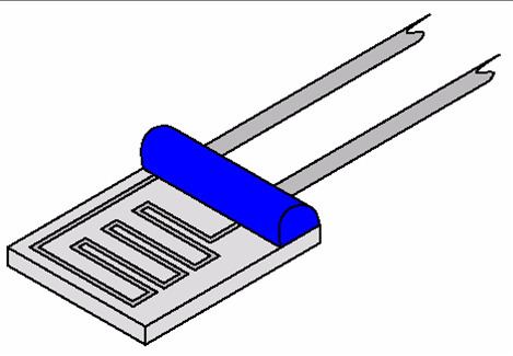
Resistance thermometers, also called resistance temperature detectors (RTDs), are sensors used to measure temperature. Many RTD elements consist of a length of fine wire wrapped around a ceramic or glass core but other constructions are also used. The RTD wire is a pure material, typically platinum, nickel, or copper. The material has an accurate resistance/temperature relationship which is used to provide an indication of temperature. As RTD elements are fragile, they are often housed in protective probes.
Contents
- Resistancetemperature relationship of metals
- Calibration
- Element types
- Function
- Advantages and limitations
- RTDs vs thermocouples
- Classifications of RTDs
- History
- Standard resistance thermometer data
- References
RTDs, which have higher accuracy and repeatability, are slowly replacing thermocouples in industrial applications below 600 °C.
Resistance/temperature relationship of metals
Common RTD sensing elements constructed of platinum, copper or nickel have a repeatable resistance versus temperature relationship (R vs T) and operating temperature range. The R vs T relationship is defined as the amount of resistance change of the sensor per degree of temperature change. The relative change in resistance (temperature coefficient of resistance) varies only slightly over the useful range of the sensor.
Platinum was proposed by Sir William Siemens as an element for resistance temperature detector at the Bakerian lecture in 1871: it is a noble metal and has the most stable resistance–temperature relationship over the largest temperature range. Nickel elements have a limited temperature range because the amount of change in resistance per degree of change in temperature becomes very non-linear at temperatures over 572 °F (300 °C). Copper has a very linear resistance–temperature relationship; however, copper oxidizes at moderate temperatures and cannot be used over 302 °F (150 °C).
Platinum is the best metal for RTDs due to its very linear resistance–temperature relationship, highly repeatable over a wide temperature range. The unique properties of platinum make it the material of choice for temperature standards over the range of −272.5 °C to 961.78 °C. It is used in the sensors that define the International Temperature Standard, ITS-90. Platinum is chosen also because of its chemical inertness.
The significant characteristic of metals used as resistive elements is the linear approximation of the resistance versus temperature relationship between 0 and 100 °C. This temperature coefficient of resistance is denoted by α and is usually given in units of Ω/(Ω·°C):
where
Pure platinum has α = 0.003925 Ω/(Ω·°C) in the 0 to 100 °C range and is used in the construction of laboratory-grade RTDs. Conversely, two widely recognized standards for industrial RTDs IEC 60751 and ASTM E-1137 specify α = 0.00385 Ω/(Ω·°C). Before these standards were widely adopted, several different α values were used. It is still possible to find older probes that are made with platinum that have α = 0.003916 Ω/(Ω·°C) and 0.003902 Ω/(Ω·°C).
These different α values for platinum are achieved by doping; basically, carefully introducing impurities into the platinum. The impurities introduced during doping become embedded in the lattice structure of the platinum and result in a different R vs. T curve and hence α value.
Calibration
To characterize the R vs T relationship of any RTD over a temperature range that represents the planned range of use, calibration must be performed at temperatures other than 0 °C and 100 °C. This is necessary to meet calibration requirements. Although RTDs are considered to be linear in operation, it must be proven that they are accurate with regard to the temperatures with which they will actually be used (see details in Comparison calibration option). Two common calibration methods are the fixed-point method and the comparison method.
Element types
There are five main categories of RTD sensors: thin-film, wire-wound, and coiled elements. While these types are the ones most widely used in industry, there are some places where other more exotic shapes are used, for example carbon resistors are used at ultra-low temperatures (−173 °C to −273 °C).
The current international standard that specifies tolerance and the temperature-to-electrical resistance relationship for platinum resistance thermometers (PRTs) is IEC 60751:2008; ASTM E1137 is also used in the United States. By far the most common devices used in industry have a nominal resistance of 100 ohms at 0 °C and are called Pt100 sensors ("Pt" is the symbol for platinum, "100" for the resistance in ohms at 0 °C). It is also possible to get Pt1000 sensors, where 1000 is for the resistance in ohms at 0 °C. The sensitivity of a standard 100 Ω sensor is a nominal 0.385 Ω/°C. RTDs with a sensitivity of 0.375 and 0.392 Ω/°C, as well as a variety of others, are also available.
Function
Resistance thermometers are constructed in a number of forms and offer greater stability, accuracy and repeatability in some cases than thermocouples. While thermocouples use the Seebeck effect to generate a voltage, resistance thermometers use electrical resistance and require a power source to operate. The resistance ideally varies nearly linearly with temperature per the Callendar-Van Dusen equation.
The platinum detecting wire needs to be kept free of contamination to remain stable. A platinum wire or film is supported on a former in such a way that it gets minimal differential expansion or other strains from its former, yet is reasonably resistant to vibration. RTD assemblies made from iron or copper are also used in some applications. Commercial platinum grades exhibit a temperature coefficient of resistance 0.00385/°C (0.385%/°C) (European Fundamental Interval). The sensor is usually made to have a resistance of 100 Ω at 0 °C. This is defined in BS EN 60751:1996 (taken from IEC 60751:1995). The American Fundamental Interval is 0.00392/°C, based on using a purer grade of platinum than the European standard. The American standard is from the Scientific Apparatus Manufacturers Association (SAMA), who are no longer in this standards field. As a result, the "American standard" is hardly the standard even in the US.
Lead-wire resistance can also be a factor; adopting three- and four-wire, instead of two-wire, connections can eliminate connection-lead resistance effects from measurements (see below); three-wire connection is sufficient for most purposes and is an almost universal industrial practice. Four-wire connections are used for the most precise applications.
Advantages and limitations
The advantages of platinum resistance thermometers include:
Limitations: RTDs in industrial applications are rarely used above 660 °C. At temperatures above 660 °C it becomes increasingly difficult to prevent the platinum from becoming contaminated by impurities from the metal sheath of the thermometer. This is why laboratory standard thermometers replace the metal sheath with a glass construction. At very low temperatures, say below −270 °C (3 K), because there are very few phonons, the resistance of an RTD is mainly determined by impurities and boundary scattering and thus basically independent of temperature. As a result, the sensitivity of the RTD is essentially zero and therefore not useful.
Compared to thermistors, platinum RTDs are less sensitive to small temperature changes and have a slower response time. However, thermistors have a smaller temperature range and stability.
RTDs vs thermocouples
The two most common ways of measuring industrial temperatures are with resistance temperature detectors (RTDs) and thermocouples. Choice between them is usually determined by four factors.
These elements nearly always require insulated leads attached. PVC, silicone rubber or PTFE insulators are used at temperatures below about 250 °C. Above this, glass fibre or ceramic are used. The measuring point, and usually most of the leads, require a housing or protective sleeve, often made of a metal alloy that is chemically inert to the process being monitored. Selecting and designing protection sheaths can require more care than the actual sensor, as the sheath must withstand chemical or physical attack and provide convenient attachment points.
The simplest resistance-thermometer configuration uses two wires. It is only used when high accuracy is not required, as the resistance of the connecting wires is added to that of the sensor, leading to errors of measurement. This configuration allows use of 100 meters of cable. This applies equally to balanced bridge and fixed bridge system.
For a balanced bridge usual setting is with R2 = R3, and R1 around the middle of the range of the RTD. So for example, if we are going to measure between 0 and 100 °C (32 and 212 °F), RTD resistance will range from 100 Ω to 138.5 Ω. We would choose R1 = 120 Ω. In that way we get a small measured voltage in the bridge.
In order to minimize the effects of the lead resistances, a three-wire configuration can be used. In this method the two leads to the sensor are on adjoining arms. There is a lead resistance in each arm of the bridge, so that the resistance is cancelled out if the two lead resistances are accurately the same. This configuration allows up to 600 metres (2,000 feet) of cable.
As in the case with the 2-wire connection, the usual setting is with R2 = R3, and R1 around the middle of the range of the RTD.
The four-wire resistance configuration increases the accuracy of measurement of resistance. Four-terminal sensing eliminates voltage drop in the measuring leads as a contribution to error. To increase accuracy further, any residual thermoelectric voltages generated by different wire types or screwed connections are eliminated by reversal of the direction of the 1 mA current and the leads to the DVM (digital voltmeter). The thermoelectric voltages will be produced in one direction only. By averaging the reversed measurements, the thermoelectric error voltages are cancelled out.
Classifications of RTDs
The highest-accuracy of all PRTs are the Standard Platinum Resistance Thermometers (SPRTs). This accuracy is achieved at the expense of durability and cost. The SPRT elements are wound from reference-grade platinum wire. Internal lead wires are usually made from platinum, while internal supports are made from quartz or fused silica. The sheaths are usually made from quartz or sometimes Inconel, depending on temperature range. Larger-diameter platinum wire is used, which drives up the cost and results in a lower resistance for the probe (typically 25.5 Ω). SPRTs have a wide temperature range (−200 °C to 1000 °C) and are approximately accurate to ±0.001 °C over the temperature range. SPRTs are only appropriate for laboratory use.
Another classification of laboratory PRTs is Secondary-Standard Platinum Resistance Thermometers (Secondary SPRTs). They are constructed like the SPRT, but the materials are more cost-effective. SPRTs commonly use reference-grade, high-purity smaller-diameter platinum wire, metal sheaths and ceramic type insulators. Internal lead wires are usually a nickel-based alloy. Secondary SPRTs are more limited in temperature range (−200 °C to 500 °C) and are approximately accurate to ±0.03 °C over the temperature range.
Industrial PRTs are designed to withstand industrial environments. They can be almost as durable as a thermocouple. Depending on the application, industrial PRTs can use thin-film or coil-wound elements. The internal lead wires can range from PTFE-insulated stranded nickel-plated copper to silver wire, depending on the sensor size and application. Sheath material is typically stainless steel; higher-temperature applications may demand Inconel. Other materials are used for specialized applications.
History
The application of the tendency of electrical conductors to increase their electrical resistance with rising temperature was first described by Sir William Siemens at the Bakerian Lecture of 1871 before the Royal Society of Great Britain. The necessary methods of construction were established by Callendar, Griffiths, Holborn and Wein between 1885 and 1900.
Standard resistance thermometer data
Temperature sensors are usually supplied with thin-film elements. The resistance elements are rated in accordance with BS EN 60751:2008 as:
Resistance-thermometer elements functioning up to 1000 °C can be supplied. The relation between temperature and resistance is given by the Callendar-Van Dusen equation:
Here
Since the B and C coefficients are relatively small, the resistance changes almost linearly with the temperature.
For positive temperature, solution of the quadratic equation yields the following relationship between temperature and resistance:
Then for a four-wire configuration with a 1 mA precision current source the relationship between temperature and measured voltage