
 | ||
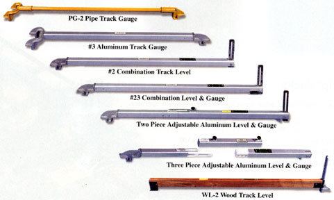
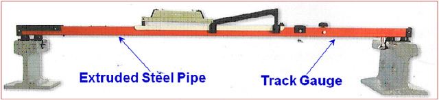
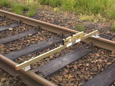
Mystery tool solved railroad track gauge and level for measuring rail superelevation on curves
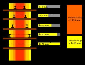
In rail transport, track gauge is the spacing of the rails on a railway track and is measured between the inner faces of the load-bearing rails.
Contents
- Mystery tool solved railroad track gauge and level for measuring rail superelevation on curves
- Nominal track gauge
- Units
- Advantages and disadvantages of different track gauges
- Early track technology
- The Stockton and Darlington Railway
- Broad gauge
- Gauge differences
- Gauge selection in other countries
- Couplers
- Terminology
- Standard gauge
- Medium gauge
- Narrow gauge
- Break of gauge
- Mixed gauge
- Maintenance standards
- Dominant gauges
- Future
- Trans Asian Railway
- East African Railway Master Plan
- Australia
- Cameroon
- India
- Nigeria
- The Americas
- Temporary way permanent way
- Timeline
- References
All vehicles on a network must have running gear that is compatible with the track gauge, and in the earliest days of railways the selection of a proposed railway's gauge was a key issue.
As the dominant parameter determining interoperability, it is still frequently used as a descriptor of a route or network.
There is a distinction between the nominal gauge and actual gauge at some locality, due to divergence of track components from the nominal. Railway engineers use a device, like a caliper, to measure the actual gauge, and this device is also referred to as a track gauge.
Nominal track gauge

The nominal track gauge is the distance between the inner faces of the rails. In current practice, it is specified at a certain distance below the rail head as the inner faces of the rail head (the gauge faces) are not necessarily vertical.
Rolling stock on the network must have running gear (wheelsets) that are compatible with the gauge, and therefore the gauge is a key parameter in determining interoperability, but there are many others—see below. In some cases in the earliest days of railways, the railway company saw itself as an infrastructure provider only, and independent hauliers provided wagons suited to the gauge. Colloquially the wagons might be referred to as "four-foot gauge wagons", say, if the track had a gauge of four feet. This nominal value does not equate to the flange spacing, as some freedom is allowed for.
An infrastructure manager might specify new or replacement track components at a slight variation from the nominal gauge for pragmatic reasons.
Units
Track is defined in old Imperial units or in universally accepted metric units or SI units.
Imperial units were established in United Kingdom by The Weights and Measures Act of 1824. The United States customary units for length did not agree with the Imperial system until 1959, when one International yard was defined as 0.9144 meters, i.e. 1 foot as 0.3048 meter and 1 inch as 25.4 mm.
The list shows the Imperial and other units that have been used for track gauge definitions:
Advantages and disadvantages of different track gauges
When selecting a gauge, there is always a trade-off between different pros and cons:
One generally wants higher speed, greater stability and larger capacity, and one wants lower cost and tighter turning radius, but there is an inverse relationship between these factors. In addition, there are other constraints, such as the load-carrying capacity of axles, which can be problematic with an excessively wide gauge.
Narrow gauge railways usually cost less to build because they are usually lighter in construction, using smaller cars and locomotives (smaller loading gauge), as well as smaller bridges, smaller tunnels (smaller structure gauge) and tighter curves. Narrow gauge is thus often used in mountainous terrain, where the savings in civil engineering work can be substantial. It is also used in sparsely populated areas, with low potential demand, and for temporary railways that will be removed after short-term use, such as for construction, the logging industry, the mining industry, or large-scale construction projects, especially in confined spaces (see Temporary way – permanent way).
Broader gauge railways are generally more expensive to build and require wider curves, but are able to handle heavier and faster traffic.
There is no single perfect gauge, because different environments and economic considerations come into play. A narrow gauge is superior if one's main considerations are economy and tight curvature (e.g. Japan relies on the 3'6" gauge due to its mountainous terrain). For direct, unimpeded routes with high traffic, a broad gauge may be preferable (which is why the BART train system uses 5 ft 6 in gauge railway gauge). The Standard, Russian, and 4'6" gauges are designed to strike a reasonable balance between these factors.
In addition to the general trade-off, another important factor is standardization. Once a standard has been chosen, and equipment, infrastructure, and training calibrated to that standard, conversion becomes difficult and expensive. This also makes it easier to adopt an existing standard than to invent a new one. This is true of many technologies, including railroad gauges. The reduced cost, greater efficiency, and greater economic opportunity offered by the use of a common standard explains why a small number of gauges predominate worldwide.
Early track technology
In the earliest days of railways, single wagons were manhandled on timber rails, almost always in connection with mineral extraction, within a mine or quarry leading from it. Guidance was not at first provided except by human muscle power, but later a number of methods of guiding the wagons were employed. The rails had to be at a spacing that suited the wagon wheels.
The timber rails wore rapidly and later flat cast-iron plates were provided to limit the wear. In some localities, the plates were made L-shaped, the upstand of the L providing the guidance; this is generally referred to as a "plateway".
As the guidance of the wagons was improved, short strings of wagons could be connected and pulled by horses, and the track could be extended from the immediate vicinity of the mine or quarry, typically to a navigable waterway. The wagons were built to a consistent pattern and the track would be made to suit the wagons: the gauge was more critical. The Penydarren Tramroad of 1802 in South Wales, a plateway, spaced these at 4 ft 4 in (1,321 mm) over the outside of the upstands.
The Penydarren Tramroad probably carried the first journey by a locomotive, in 1804, and it was successful for the locomotive, but unsuccessful for the track: the plates were not strong enough to carry its weight. A considerable progressive step was made when cast iron edge rails were first employed; these had the major axis of the rail section configured vertically, giving a much stronger section to resist bending forces, and this was further improved when fish-belly rails were introduced.
Edge rails required a close match between rail spacing and the configuration of the wheelsets, and the importance of the gauge was reinforced. Railways were still seen as local concerns: there was no appreciation of a future connection to other lines, and selection of the track gauge was still a pragmatic decision based on local requirements and prejudices, and probably determined by existing local designs of (road) vehicles.
Thus, the Monkland and Kirkintilloch Railway (1826) in the West of Scotland used 4 ft 6 in (1,372 mm); the Dundee and Newtyle Railway (1831) in the north-east of Scotland adopted 4 ft 6 1⁄2 in (1,384 mm); the Redruth and Chasewater Railway (1825) in Cornwall chose 4 ft (1,219 mm).
The Arbroath and Forfar Railway opened in 1838 with a gauge of 5 ft 6 in (1,676 mm), and the Ulster Railway of 1839 used 6 ft 2 in (1,880 mm)
The Stockton and Darlington Railway
Locomotives were being developed in the first decades of the nineteenth century; they took various forms, but George Stephenson developed a successful locomotive on the Killingworth Wagonway, where he worked. His designs were so successful that they became the standard, and when the Stockton and Darlington Railway was opened in 1825, it used his locomotives, with the same gauge as the Killingworth line, 4 ft 8 in (1,422 mm).
The Stockton and Darlington line was immensely successful, and when the Liverpool and Manchester Railway, the first intercity line, was promoted (it opened in 1830), it used the same gauge. It was also hugely successful, and the gauge (now eased to 4 ft 8 1⁄2 in (1,435 mm)), became the automatic choice: "standard gauge".
Broad gauge
The Liverpool and Manchester was quickly followed by other trunk railways, with the Grand Junction Railway and the London and Birmingham Railway forming a huge critical mass of standard gauge. When Bristol promoters planned a line from London, they employed the innovative engineer Isambard Kingdom Brunel. He decided on a wider gauge, to give greater stability, and the Great Western Railway adopted a gauge of 7 ft (2,134 mm), later eased to 7 ft 1⁄4 in (2,140 mm). This became known as broad gauge. The GWR was successful and became greatly extended, directly and through friendly associated companies, widening the scope of broad gauge.
Gauge differences
At the same time, other parts of Britain built railways to standard gauge, and British technology was exported to European countries and parts of North America, also using standard gauge. Britain polarised into areas that had broad gauge lines or standard gauge lines. In this context, standard gauge was referred to as narrow gauge to indicate the contrast. Some smaller concerns selected other non-standard gauges: the Eastern Counties Railway adopted 5 ft (1,524 mm). Most of them converted to standard gauge at an early date, but the GWR's broad gauge continued to grow.
The larger railway companies wished to expand geographically, and large areas were considered to be under their control. When a new independent line was proposed to open up an unconnected area, the gauge was crucial in determining the allegiance that the line would adopt: if it was broad gauge, it must be friendly to the Great Western railway; if narrow (standard) gauge, it must favour the other companies. The battle to persuade or coerce that choice became very intense, and became referred to as "the gauge wars".
As passengers and freight between the gauges became increasingly important, the difficulty of moving from one gauge to the other — the break of gauge – became more prominent and more objectionable. In 1845 a Royal Commission on Railway Gauges was created to look into the growing problem and this led to the Regulating the Gauge of Railways Act 1846, which forbade the construction of broad gauge lines unconnected with the broad gauge network, and the broad gauge network was eventually converted—a process called gauge conversion—to standard, progressively until 1892. The same Act mandated the gauge of 5 ft 3 in (1,600 mm) for use in Ireland.
Gauge selection in other countries
As railways were built in other countries, the gauge selected was pragmatic; the track would have to fit the rolling stock. If locomotives were imported from elsewhere, especially in the early days, the track would be built to fit them. In some cases standard gauge was adopted, but many countries or companies chose a different gauge as their national gauge, either by governmental policy, or as a matter of individual choice. Government officials in Spain and Russia were concerned that the rail lines they were planning could be used by an invader, and purposely chose gauges that were different from their neighbors.
Narrow gauges were widely used in mountainous regions as construction costs tended to be lower and they provided for tighter turns that were often required.
Couplers
To keep the rail traffic compatible within a network, not only the track gauge needs to be the same, but also the couplers, at least for locomotive hauled vehicles. For this reason, all the standard gauge railways in Europe use the standard buffers and chain coupler for locomotive hauled vehicles, while narrow gauge railways use a variation of couplers, since they often are isolated from each other, so standardisation doesn't matter. Similarly standard gauge railways in North America, Canada and Mexico included, use the janney coupler or the compatible tightlock coupling for locomotive hauled equipment.
Terminology
The terms standard gauge, broad gauge and narrow gauge do not have any fixed meaning. A "standard" gauge is only standard in a geographical region where it is dominant, but it is generally understood to be 1,435 mm (4 ft 8 1⁄2 in). An infrastructure owner would be ill-advised to order track materials simply as "standard gauge", but would normally specify the required critical dimensions of the components.
Broad gauge and narrow gauge are relative to the generally adopted standard.
In the British area of influence in southern Africa, 3 ft 6 in (1,067 mm) was widely adopted.
The terms structure gauge and loading gauge have little connection with track gauge. They are both widely used, but imprecise, terms. Structure gauge describes the cross-section envelope into which new or altered structures (bridges, lineside equipment etc.) must not encroach. Loading gauge is the corresponding cross-sectional profile within which rail vehicles and their loads must be contained. If an exceptional load or a new type of vehicle is being assessed to run, it must conform to the route's loading gauge.
Historically, a space between the two profiles was required to allow for dynamic effects, extreme wear and surveying tolerances, but in current practice, all tolerances are incorporated into the vehicle operating profile and no other allowance is necessary.
Nowadays, there are other parameters that must be assessed for interoperability, including electro-magnetic compatibility, compliance with control system parameters, axle load and loading envelope.
In British practice, the space between the rails of a track is colloquially referred to as the "four-foot", and the space between two tracks the "six-foot", descriptions relating to the respective dimensions.
Standard gauge
In common usage the term "standard gauge" refers to 1,435 mm (4 ft 8 1⁄2 in).
Medium gauge
The term medium gauge had different meanings throughout history, depending on the local dominant gauge in use.
Narrow gauge
During the period known as "the Battle of the Gauges", Stephenson's standard gauge was commonly known as "narrow gauge", while Brunel's railway's 7 ft 1⁄4 in (2,140 mm) gauge was termed "broad gauge".
As the gauge of a railway is reduced the costs of construction can be reduced since narrow gauges allow smaller-radius curves, allowing obstacles to be avoided rather than having to be built over or through (valleys and hills); the reduced cost is particularly noticeable in mountainous regions, and many narrow gauge railways were built in Wales, the Rocky Mountains of North America, Central Europe and South America.
Industrial railways are often narrow gauge. Sugar cane and banana plantations are often served by narrow gauges such as 2 ft (610 mm), as there is little through traffic to other systems.
The most widely used narrow gauges on public railways are
Break of gauge
Through operation between railway networks with different gauges was originally impossible; goods had to be transhipped and passengers had to change trains. This was obviously a major obstacle to convenient transport, and in Great Britain, led to political intervention.
On narrow gauge lines, Rollbocks or transporter wagons are used: standard gauge wagons are carried on narrow gauge lines on these special vehicles, generally with rails of the wider gauge to enable those vehicles to roll on and off at transfer points.
On the Transmongolian Railway, Russia and Mongolia use 1,520 mm (4 ft 11 27⁄32 in) while China uses standard gauge. At the border, each carriage is lifted and its bogies are changed. The operation can take several hours for a whole train of many carriages.
Other examples include crossings into or out of the former Soviet Union: Ukraine/Slovakia border on the Bratislava-L'viv train, and the Romania/Moldova border on the Chişinău-Bucharest train.
A system developed by Talgo and Construcciones y Auxiliar de Ferrocarriles (CAF) of Spain uses variable gauge wheelsets; at the border between France and Spain, through passenger trains are drawn slowly through apparatus that alters the gauge of the wheels, which slide laterally on the axles. This is fully described in Automatic Gauge Changeover for Trains in Spain.
A similar system is used between China and Central Asia, and between Poland and Ukraine, using the SUW 2000 and INTERGAUGE variable axle systems. China and Poland use standard gauge, while Central Asia and Ukraine use 1,520 mm (4 ft 11 27⁄32 in).
Mixed gauge
Where a railway corridor is used by trains of two gauges, mixed gauge (or dual gauge) track can be provided, in which three rails are supported in the same track structure. This arose particularly when individual railway companies chose different gauges and were subsequently required to share a route; this is most commonly found at the approaches to city terminals, where land space is limited.
Trains of different gauges sharing the same track can save considerable expense compared to using separate tracks for each gauge, but introduces complexities in track maintenance and signalling, and may require speed restrictions for some trains. If the difference between the two gauges is large enough, for example between 1,435 mm (4 ft 8 1⁄2 in) standard gauge and 3 ft 6 in (1,067 mm), three-rail dual-gauge is possible, but if not, for example between 3 ft 6 in (1,067 mm) and 1,000 mm (3 ft 3 3⁄8 in) metre gauge, four-rail triple-gauge is used. Dual-gauge rail lines are used in Switzerland, Australia, Argentina, Brazil, Japan, North Korea, Spain, Tunisia and Vietnam.
On the GWR, there was an extended period between political intervention in 1846 that prevented major expansion of its 7 ft 1⁄4 in (2,140 mm) broad gauge and the final gauge conversion to standard gauge in 1892.
During this period, there were many locations where practicality required mixed gauge operation, and in station areas, the track configuration was extremely complex. This was compounded by the fact that the common rail had to be at the platform side in stations, so in many cases, standard-gauge trains needed to be switched from one side of the track to the other at the approach. A special fixed point arrangement was devised for the purpose, where the track layout was simple enough. Jenkins and Langley give an illustration and description.
In some cases, mixed gauge trains operated, conveying wagons of both gauges. For example, MacDermot says:
In November 1871 a novelty in the shape of a mixed-gauge goods train was introduced between Truro and Penzance. It was worked by a narrow-gauge engine, and behind the narrow-gauge trucks came a broad-gauge match-truck with wide buffers and sliding shackles, followed by the broad-gauge trucks. Such trains continued to run in West Cornwall until the abolition of the Broad Gauge; they had to stop or come down to walking pace at all stations where fixed points existed and the narrow portion side-stepped to right or left.
Maintenance standards
Infrastructure owners specify permitted variances from the nominal gauge, and the required interventions when non-compliant gauge is detected. For example, the Federal Railroad Administration in the USA specifies that the actual gauge of track that is rated for a maximum of 60 mph (96.6 km/h) must be between 4 ft 8 in (1,422 mm) and 4 ft 9.5 in (1,460 mm).
Dominant gauges
Approximately 55% of the world's railways use 4 ft 8 1⁄2 in (1,435 mm) standard gauge.
Total for each type of gauge.
Future
Further convergence of rail gauge use seems likely, as countries seek to build inter-operable networks, and international organisations seek to build macro-regional and continental networks. The European Union has set out to develop inter-operable freight and passenger rail networks across its area, and is seeking to standardise gauge, signalling and electrical power systems. As countries build High-speed rails, they also tend to converge these rails' gauge to standard gauge, with the exceptions of Uzbekistan and Russia.
EU funds have been dedicated to assist Lithuania, Latvia, and Estonia in the building of some key railway lines (Rail Baltica) of standard gauge, and to assist Spain and Portugal in the construction of high-speed lines to connect Iberian cities to one another and to the French high-speed lines. The EU has developed plans for improved freight rail links between Spain, Portugal, and the rest of Europe.
Gauge conversion of existing lines is extremely expensive and it is likely that only primary trunk routes will be converted, with new strategic lines being built to standard gauge.
Trans-Asian Railway
The United Nations Economic and Social Commission for Asia and the Pacific (UNESCAP) is planning a Trans-Asian Railway that will link Europe and the Pacific, with a Northern Corridor from Europe to the Korean Peninsula, a Southern Corridor from Europe to Southeast Asia, and a North–South corridor from Northern Europe to the Persian Gulf. All these would encounter breaks of gauge as they cross Asia. Current plans have mechanized facilities at the breaks of gauge to move containers from train to train rather than widespread gauge conversion.
East African Railway Master Plan
The East African Railway Master Plan is a proposal for rebuilding and expanding railway lines connecting Ethiopia, Djibouti, Kenya, Uganda, Rwanda, Burundi, Tanzania, South Sudan and beyond. The plan is managed by infrastructure ministers from participating East African Community countries in association with transport consultation firm CPCS Transcom. Older railways are of 1,000 mm (3 ft 3 3⁄8 in) metre gauge or 3 ft 6 in (1,067 mm) gauge. Newly rebuilt lines will use Standard gauge. The standard gauge Addis Ababa-Djibouti and Mombasa-Nairobi railways are scheduled to begin regular freight and passenger services in 2017.
Australia
Lines for iron ore to Oakajee port in Western Australia are proposed to form a combined dual-gauge network.
Cameroon
India
India's railways are mostly 5 ft 6 in (1,676 mm) broad gauge. Metre- and narrow-gauge rail lines are being converted to 1,676 mm (5 ft 6 in) broad gauge. The Urban rail in India is being built using standard gauge. In addition, India is connecting its national network to two neighboring countries:
Nigeria
Nigeria's railways are mostly 3 ft 6 in (1,067 mm) Cape gauge. The Lagos–Kano Standard Gauge Railway is a gauge conversion project by the Nigerian Government to create a north-south standard gauge rail link. The first converted segment, between Abuja and Kaduna, was completed in July 2016.
The Americas
Temporary way – permanent way
The temporary way is the temporary track often used for construction, replaced by the permanent way (the structure consisting of the rails, fasteners, sleepers/ties and ballast (or slab track), plus the underlying subgrade) when construction nears completion. In many cases narrow-gauge track is used for a temporary way because of the convenience in laying it and changing its location over unimproved ground.
In restricted spaces such as tunnels, the temporary way might be double track even though the tunnel will ultimately be single track. The Airport Rail Link in Sydney had construction trains of 900 mm (2 ft 11 7⁄16 in) gauge, which were replaced by permanent tracks of 1,435 mm (4 ft 8 1⁄2 in) gauge.
During World War I trench warfare led to a relatively static disposition of infantry, requiring considerable logistics to bring them support staff and supplies (food, ammunition, earthworks materials, etc.). Dense light railway networks using temporary narrow gauge track sections were established by both sides for this purpose.
In 1939 it was proposed to construct the western section of the Yunnan–Burma Railway using a gauge of 15 1⁄4 in (387 mm), since such tiny or "toy" gauge facilitates the tightest of curves in difficult terrain.