
 | ||
The minimum railway curve radius is the shortest allowable design radius for railway tracks under a particular set of conditions. It has an important bearing on constructions costs and operating costs and, in combination with superelevation (difference in elevation of the two rails) in the case of train tracks, determines the maximum safe speed of a curve. Minimum radius of curve is one parameter in the design of railway vehicles as well as trams. Monorails and guideways are also subject to minimum radii.
Contents
History
The first proper railway was the Liverpool and Manchester Railway which opened in 1830. Like the trams that had preceded it over a hundred years, the L&M had gentle curves and gradients. Among other reasons for the gentle curves were the lack of strength of the track, which might have overturned if the curves were too sharp causing derailments. There was no signalling at this time, so drivers had to be able to see ahead to avoid collisions with previous trains. The gentler the curves, the longer the visibility. The earliest rails were made in short lengths of wrought iron, which does not bend like later steel rails introduced in the 1850s.
Factors affecting the minimum curve radius
Minimum curve radii for railroads are governed by the speed operated and by the mechanical ability of the rolling stock to adjust to the curvature. In North America, equipment for unlimited interchange between railroad companies are built to accommodate 350-foot (106.7 m) radius, but normally 410-foot (125.0 m) radius is used as a minimum, as some freight cars are handled by special agreement between railroads that cannot take the sharper curvature. For handling of long freight trains, a minimum 717-foot (218.5 m) radius is preferred.
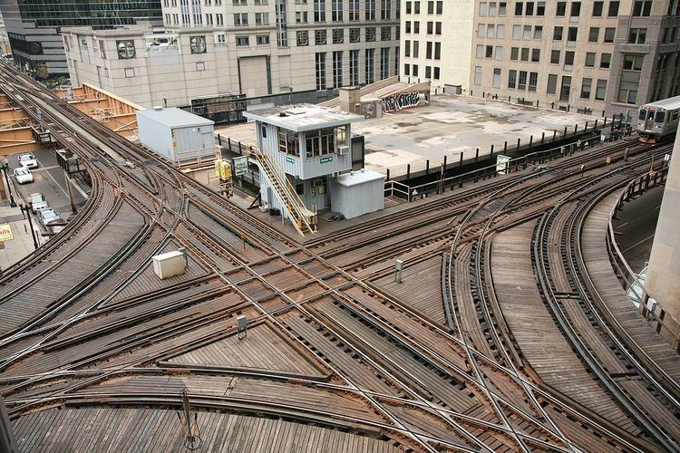
The sharpest curves tend to be on the narrowest of narrow gauge railways, where almost everything is proportionately smaller.
Steam locomotives
As the need for more powerful (steam) locomotives grew, the need for more driving wheels on a longer, fixed wheelbase grew too. But long wheel bases are unfriendly to sharp curves. Various types of articulated locomotives (e.g. Mallet, Garratt and Shay) were devised to avoid having to operate multiple locomotives with multiple crews.
More recent diesel and electric locomotives do not have a wheelbase problem and can easily be operated in multiple with a single crew.
Couplings
Not all couplers can handle very sharp curves. This is particularly true of the European buffer and chain couplers, where the buffers extend the profile of the railcar body. For a line with maximum speed 60 km/h (37 mph), buffer-and-chain couplings reduce the minimum radius to around 200 m, almost double the North American figure given above. As narrow gauge railways, tramways and metros normally do not interchange with mainline railroads, instances of these types of railroad in Europe often use bufferless central couplers and build to a tighter standard.
Train lengths
A long heavy freight train, especially those with wagons of mixed loading, may struggle on sharp curves, as the drawgear forces may pull intermediate wagons off the rails. Common solutions include:
A similar problem occurs with harsh changes in gradients (vertical curves).
Speed and cant
As a heavy train goes round a bend at speed, the reactive centrifugal force can cause negative effects: passengers and cargo may feel unpleasant forces, the inside and outside rails will wear unequally, and insufficiently anchored track may move.‹See TfD› To counter this, a cant (superelevation) is used. Ideally the train should be tilted such that resultant (combined) force acts straight "down" through the bottom of the train, so the wheels, track, train and passengers feel little or no sideways force ("down" and "sideways" are given with respect to the plane of the track and train). Some trains are capable of tilting to enhance this effect for passenger comfort. Because freight and passenger trains tend to move at different speeds and weigh dramatically different, a cant cannot be ideal for both types of rail traffic.
The relationship between speed and tilt can be calculated mathematically. We start with the formula for a balancing centripetal force: θ is the angle by which the train is tilted due to the cant, r is the curve radius in meters, v is the speed in meters per second, and g is the standard gravity, approximately equal to 9.80665 m/s²:
Rearranging for r gives:
Geometrically, tan θ can be expressed (approximately, for small angles) in terms of the track gauge G, the cant ha and cant deficiency hb, all in millimeters:
This approximation for tan θ gives:
This table shows examples of curve radii. The values used when building high-speed railways vary, and depend on desired wear and safety levels.
Tramways typically do not exhibit cant, due to the low speeds involved.
Transition curves
A curve should not become a straight all at once, but should gradually increase in radius over time (a distance of around 40 m - 80 m for a line with a maximum speed of about 100 km/h). Even worse than curves with no transition are reverse curves with no intervening straight track. The superelevation must also be transitioned. Higher speeds require longer transitions.
Vertical curves
As a train negotiates a curve, the force it exerts on the track changes. Too tight a 'crest' curve could result in the train leaving the track as it drops away beneath it; too tight a 'trough' and the train will plough downwards into the rails and damage them. More precisely, the support force R exerted by the track on a train as a function of the curve radius r, the train mass m, and the speed v, is given by
with the second term positive for troughs, negative for crests. For passenger comfort the ratio of the gravitational acceleration g to the centripetal acceleration v2/r needs to be kept as small as possible, else passengers will feel large 'changes' in their weight.
As trains cannot climb steep slopes, they have little occasion to go over significant vertical curves. However, high-speed trains are sufficiently high-powered that steep slopes are preferable to the reduced speed necessary to navigate horizontal curves around obstacles, or the higher construction costs necessary to tunnel through or bridge over them. High Speed 1 (section 2) in the UK has a minimum vertical curve radius of 10,000 m (32,808 ft) and High Speed 2, with the higher speed of 400 km/h (250 mph), stipulates much larger 56,000 m (183,727 ft) radii. In both these cases the experienced change in 'weight' is less than 7%.
Rail well cars also risk low clearance at the tops of tight crests.