
 | ||
Thermoacoustics is the interaction between temperature, density and pressure variations of acoustic waves. Thermoacoustic heat engines can readily be driven using solar energy or waste heat and they can be controlled using proportional control. They can use heat available at low temperatures which makes it ideal for heat recovery and low power applications. The components included in thermoacoustic engines are usually very simple compared to conventional engines. The device can easily be controlled and maintained.
Contents
- Historical review of thermoacoustics
- Sound
- Penetration depths
- Thermoacoustic systems
- Standing wave systems
- Travelling wave systems
- References
Thermoacoustic effects can be observed when partly molten glass tubes are connected to glass vessels. Sometimes spontaneously a loud and monotone sound is produced. A similar effect is observed if a stainless steel tube is with one side at room temperature (293 K) and with the other side in contact with liquid helium at 4.2 K. In this case, spontaneous oscillations are observed which are named "Taconis oscillations". The mathematical foundation of thermoacoustics is by Nikolaus Rott. Later, the field was inspired by the work of Wheatley and Swift and his co-workers. Technologically thermoacoustic devices have the advantage that they have no moving parts which makes them attractive for applications where reliability is of key importance.
Historical review of thermoacoustics
Thermoacoustic-induced oscillations have been observed for centuries. Glass blowers produced heat generated sound when blowing a hot bulb at the end of a cold narrow tube. This phenomenon also has been observed in cryogenic storage vessels, where oscillations are induced by the insertion of a hollow tube open at the bottom end in liquid helium, called Taconis oscillations, but the lack of heat removal system causes the temperature gradient to diminish and acoustic wave to weaken and then to stop completely. Byron Higgins made the first scientific observation of heat energy conversion into acoustical oscillations. He investigated the "singing flame" phenomena in a portion of a hydrogen flame in a tube with both ends open. Putnam and Dennis gave a survey of the related phenomena. Rijke introduced this phenomenon into a greater scale by using a heated wire screen to induce strong oscillations in a tube. Feldman mentioned in his related review that a convective air current through the pipe is the main inducer of this phenomenon. The oscillations are strongest when the screen is at one fourth of the tube length. Research performed by Sondhauss in 1850 is known to be the first to approximate the modern concept of thermoacoustic oscillation. Sondhauss experimentally investigated the oscillations related to glass blowers. Sondhauss observed that sound frequency and intensity depends on the length and volume of the bulb. Lord Rayleigh gave a qualitative explanation of the Sondhauss thermoacoustic oscillations phenomena, where he stated that producing any type of thermoacoustic oscillations needs to meet a criterion: "If heat be given to the air at the moment of greatest condensation or taken from it at the moment of greatest rarefaction, the vibration is encouraged". This shows that he related thermoacoustics to the interplay of density variations and heat injection. The formal theoretical study of thermoacoustics started by Kramers in 1949 when he generalized the Kirchhoff theory of the attenuation of sound waves at constant temperature to the case of attenuation in the presence of a temperature gradient. Rott made a breakthrough in the study and modeling of thermodynamic phenomena by developing a successful linear theory. After that, the acoustical part of thermoacoustics was linked in a broad thermodynamic framework by Swift.
Sound
Usually sound is understood in terms of pressure variations accompanied by an oscillating motion of a medium (gas, liquid or solid). In order to understand thermoacoustic machines, it is of importance to focus on the temperature-position variations rather than the usual pressure-velocity variations.
The sound intensity of ordinary speech is 65 dB. The pressure variations are about 0.05 Pa, the displacements 0.2 μm, and the temperature variations about 40 μK. So, the thermal effects of sound cannot be observed in daily life. However, at sound levels of 180 dB, which are normal in thermoacoustic systems, the pressure variations are 30 kPa, the displacements more than 10 cm, and the temperature variations 24 K.
The one-dimensional wave equation for sound reads
with t time, v the gas velocity, x the position, and c the sound velocity given by c²=γp₀/ρ₀. For an ideal gas, c²=γRT₀/M with M the molar mass. In these expressions, p₀, T₀, and ρ₀ are the average pressure, temperature, and density respectively. In monochromatic plane waves, with angular frequency ω and with ω=kc, the solution is
The pressure variations are given by
The deviation δx of a gas-particle with equilibrium position x is given by
and the temperature variations are
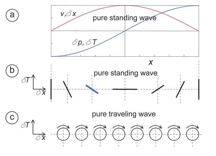
The last two equations form a parametric representation of a tilted ellipse in the δT – δx plane with t as the parameter.
If
where γ is the ratio of the gas specific heat at fixed pressure to the specific heat at fixed volume and A is the area of the cross section of the sound duct. Since in a standing wave,
If
Penetration depths
The thermoacoustic effect inside the stack takes place mainly in the region that is close to the solid walls of the stack. The layers of gas too far away from the stack walls experience adiabatic oscillations in temperature that result in no heat transfer to or from the walls, which is undesirable.Therefore, an important characteristic for any thermoacoustic element is the value of the thermal and viscous penetration depths. The thermal penetration depth δκ is the thickness of the layer of the gas where heat can diffuse through during half a cycle of oscillations. Viscous penetration depth δv is the thickness of the layer where viscosity effect is effective near the boundaries. In case of sound, the characteristic length for thermal interaction is given by the thermal penetration depth δκ
Here κ is the thermal conductivity, Vm the molar volume, and Cp the molar heat capacity at constant pressure. Viscous effects are determined by the viscous penetration depth δν
with η the gas viscosity and ρ its density. The Prandtl number of the gas is defined as
The two penetration depths are related as follows
For many working fluids, like air and helium, Pr is of order 1, so the two penetration depths are about equal. For helium at normal temperature and pressure, Pr≈0.66. For typical sound frequencies the thermal penetration depth is ca. 0.1 mm. That means that the thermal interaction between the gas and a solid surface is limited to a very thin layer near the surface. The effect of thermoacoustic devices is increased by putting a large number of plates (with a plate distance of a few times the thermal penetration depth) in the sound field forming a stack. Stacks play a central role in so-called standing-wave thermoacoustic devices.
Thermoacoustic systems
Acoustic oscillations in a media are a set of time depending properties, which may transfer energy along its path. Along the path of an acoustic wave, pressure and density are not the only time dependent property, but also entropy and temperature. Temperature changes along the wave can be invested to play the intended role in the thermoacoustic effect. The interplay of heat and sound is applicable in both conversion ways. The effect can be used to produce acoustic oscillations by supplying heat to the hot side of a stack, and sound oscillations can be used to induce a refrigeration effect by supplying a pressure wave inside a resonator where a stack is located. In a thermoacoustic prime mover, a high temperature gradient along a tube where a gas media is contained induces density variations. Such variations in a constant volume of matter force changes in pressure. The cycle of thermoacoustic oscillation is a combination of heat transfer and pressure changes in a sinusoidal pattern. Self-induced oscillations can be encouraged, according to Lord Raleigh, by the appropriate phasing of heat transfer and pressure changes.
Standing-wave systems
The thermoacoustic engine (TAE) is a device that converts heat energy into work in the form of acoustic energy. A thermoacoustic engine is operating using the effects that arise from the resonance of a standing-wave in a gas. A standing-wave thermoacoustic engine typically has a thermoacoustic element called the "stack". A stack is a solid component with pores that allow the operating gas fluid to oscillate while in contact with the solid walls. The oscillation of the gas is accompanied with the change of its temperature. Due to the introduction of solid walls into the oscillating gas, the plate modifies the original, unperturbed temperature oscillations in both magnitude and phase for the gas about a thermal penetration depth δ=√(2k/ω) away from the plate, where k is the thermal diffusivity of the gas and ω=2πf is the angular frequency of the wave. Thermal penetration depth is defined as the distance that heat can diffuse though the gas during a time 1/ω. In air oscillating at 1000 Hz, the thermal penetration depth is about 0.1 mm. Standing-wave TAE must be supplied with the necessary heat to maintain the temperature gradient on the stack. This is done by two heat exchangers on both sides of the stack.
If we put a thin horizontal plate in the sound field, the thermal interaction between the oscillating gas and the plate leads to thermoacoustic effects. If the thermal conductivity of the plate material would be zero, the temperature in the plate would exactly match the temperature profiles as in Fig. 1b. Consider the blue line in Fig. 1b as the temperature profile of a plate at that position. The temperature gradient in the plate would be equal to the so-called critical temperature gradient. If we would fix the temperature at the left side of the plate at ambient temperature Ta (e.g. using a heat exchanger), then the temperature at the right would be below Ta. In other words: we have produced a cooler. This is the basis of thermoacoustic cooling as shown in Fig. 2b which represents a thermoacoustic refrigerator. It has a loudspeaker at the left. The system corresponds with the left half of Fig. 1b with the stack in the position of the blue line. Cooling is produced at temperature TL.
It is also possible to fix the temperature of the right side of the plate at Ta and heat up the left side so that the temperature gradient in the plate would be larger than the critical temperature gradient. In that case, we have made an engine (prime mover) which can e.g. produce sound as in Fig. 2a. This is a so-called thermoacoustic prime mover. Stacks can be made of stainless steel plates but the device works also very well with loosely packed stainless steel wool or screens. It is heated at the left, e.g., by a propane flame and heat is released to ambient temperature by a heat exchanger. If the temperature at the left side is high enough, the system starts to produces a loud sound.
Thermoacoustic engines still suffer from some limitations, including that:
The performance of thermoacoustic engines usually is characterized through several indicators as follows:
Travelling-wave systems
Figure 3 is a schematic drawing of a travelling-wave thermoacoustic engine. It consists of a resonator tube and a loop which contains a regenerator, three heat exchangers, and a bypass loop. A regenerator is a porous medium with a high heat capacity. As the gas flows back and forth through the regenerator, it periodically stores and takes up heat from the regenerator material. In contrast to the stack, the pores in the regenerator are much smaller than the thermal penetration depth, so the thermal contact between gas and material is very good. Ideally, the energy flow in the regenerator is zero, so the main energy flow in the loop is from the hot heat exchanger via the pulse tube and the bypass loop to the heat exchanger at the other side of the regenerator (main heat exchanger). The energy in the loop is transported via a travelling wave as in Fig. 1c, hence the name travelling-wave systems. The ratio of the volume flows at the ends of the regenerator is TH/Ta, so the regenerator acts as a volume-flow amplifier. Just like in the case of the standing-wave system, the machine "spontaneously" produces sound if the temperature TH is high enough. The resulting pressure oscillations can be used in a variety of ways, such as in producing electricity, cooling, and heat pumping.