
 | ||
Thermoacoustic engines (sometimes called "TA engines") are thermoacoustic devices which use high-amplitude sound waves to pump heat from one place to another, or conversely use a heat difference to induce high-amplitude sound waves. In general, thermoacoustic engines can be divided into standing wave and travelling wave devices. These two types of thermoacoustics devices can again be divided into two thermodynamic classes, a prime mover (or simply heat engine), and a heat pump. The prime mover creates work using heat, whereas a heat pump creates or moves heat using work. Compared to vapor refrigerators, thermoacoustic refrigerators have no ozone-depleting or toxic coolant and few or no moving parts therefore require no dynamic sealing or lubrication.
Contents
Overview of device
A thermoacoustic device basically consists of heat exchangers, a resonator, and a stack (on standing wave devices) or regenerator (on travelling wave devices). Depending on the type of engine a driver or loudspeaker might be used as well to generate sound waves.
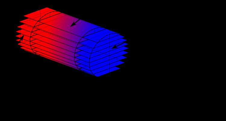
Consider a tube closed at both ends. Interference can occur between two waves traveling in opposite directions at certain frequencies. The interference causes resonance creating a standing wave. Resonance only occurs at certain frequencies called resonance frequencies, and these are mainly determined by the length of the resonator.
The stack is a part consisting of small parallel channels. When the stack is placed at a certain location in the resonator, while having a standing wave in the resonator, a temperature difference can be measured across the stack. By placing heat exchangers at each side of the stack, heat can be moved. The opposite is possible as well, by creating a temperature difference across the stack, a sound wave can be induced. The first example is a simple heat pump, while the second is a prime mover.
Heat pumping
To be able to create or move heat, work must be done, and the acoustic power provides this work. When a stack is placed inside a resonator a pressure drop occurs. Interference between the incoming and reflected wave is now imperfect since there is a difference in amplitude causing the standing wave to travel little, giving the wave acoustic power.
In the acoustic wave, parcels of gas adiabatically compress and expand. Pressure and temperature change simultaneously; when pressure reaches a maximum or minimum, so does the temperature. Heat pumping along a stack in a standing wave device can now be described using the Brayton cycle.
Below is the counter-clockwise Brayton cycle consisting of four processes for a refrigerator when a parcel of gas is followed between two plates of a stack.
- Adiabatic compression of the gas. When a parcel of gas is displaced from its rightmost position to its leftmost position, the parcel is adiabatic compressed and thus the temperature increases. At the leftmost position the parcel now has a higher temperature than the warm plate.
- Isobaric heat transfer. The parcel's temperature is higher than that of the plate causing it to transfer heat to the plate at constant pressure losing temperature.
- Adiabatic expansion of the gas. The gas is displaced back from the leftmost position to the rightmost position and due to adiabatic expansion the gas is cooled to a temperature lower than that of the cold plate.
- Isobaric heat transfer. The parcel's temperature is now lower than that of the plate causing heat to be transferred from the cold plate to the gas at a constant pressure, increasing the parcel's temperature back to its original value.
Travelling wave devices can be described using the Stirling cycle.
Temperature gradient
An engine and heat pump both typically use a stack and heat exchangers. The boundary between a prime mover and heat pump is given by the temperature gradient operator, which is the mean temperature gradient divided by the critical temperature gradient.
The mean temperature gradient is the temperature difference across the stack divided by the length of the stack.
The critical temperature gradient is a value depending on certain characteristics of the device like frequency, cross-sectional area and gas properties.
If the temperature gradient operator exceeds one, the mean temperature gradient is larger than the critical temperature gradient and the stack operates as a prime mover. If the temperature gradient operator is less than one, the mean temperature gradient is smaller than the critical gradient and the stack operates as a heat pump.
Theoretical efficiency
In thermodynamics the highest achievable efficiency is the Carnot efficiency. The efficiency of thermoacoustic engines can be compared to Carnot efficiency using the temperature gradient operator.
The efficiency of a thermoacoustic engine is given by
The coefficient of performance of a thermoacoustic heat pump is given by
Derivations
Using the Navier-Stokes equations for fluids, Rott was able to derive equations specific for thermoacoustics. Swift continued with these equations, deriving expressions for the acoustic power in thermoacoustic devices.
Efficiency in practice
The most efficient thermoacoustic devices built to date have an efficiency approaching 40% of the Carnot limit, or about 20% to 30% overall (depending on the heat engine temperatures).
Higher hot-end temperatures may be possible with thermoacoustic devices because there are no moving parts, thus allowing the Carnot efficiency to be higher. This may partially offset their lower efficiency, compared to conventional heat engines, as a percentage of Carnot.
The ideal Stirling cycle, approximated by traveling wave devices, is inherently more efficient than the ideal Brayton cycle, approximated by standing wave devices. However, the narrower pores required to give good thermal contact in a travelling wave regenerator, as compared to a standing wave stack which requires deliberately imperfect thermal contact, also gives rise to greater frictional losses, reducing the efficiency of a practical engine. The toroidal geometry often used in traveling wave devices, but not required for standing wave devices, can also give rise to losses due to Gedeon streaming around the loop.
Research in thermoacoustics
Modern research and development of thermoacoustic systems is largely based upon the work of Rott (1980) and later Greg Swift (1988), in which linear thermoacoustic models were developed to form a basic quantitative understanding, and numeric models for computation. Commercial interest has resulted in niche applications such as small to medium scale cryogenic applications.
History
The history of thermoacoustic hot air engines started about 1887, when Lord Rayleigh discussed the possibility of pumping heat with sound. Little further research occurred until Rott's work in 1969.
A very simple thermoacoustic hot air engine is the Rijke tube that converts heat into acoustic energy. This device however uses natural convection.
Current research
Orest Symko at University of Utah began a research project in 2005 called Thermal Acoustic Piezo Energy Conversion (TAPEC).
Score Ltd. was awarded £2M in March 2007 to research a cooking stove that will also deliver electricity and cooling using the Thermo-acoustic effect for use in developing countries.
A radioisotope-heated thermoacoustic system has been proposed and prototyped for deep space exploration missions by Airbus. The system has theoretical slight advantages over other generator systems like existing thermocouple based systems, or proposed Stirling engine used in ASRG prototype.