
 | ||
A submarine power cable is a major transmission cable for carrying electric power below the surface of the water. These are called "submarine" because they usually carry electric power beneath salt water (arms of the ocean, seas, straits, etc.) but it is also possible to use submarine power cables beneath fresh water (large lakes and rivers). Examples of the latter exist that connect the mainland with large islands in the St. Lawrence River.
Contents
Design technologies
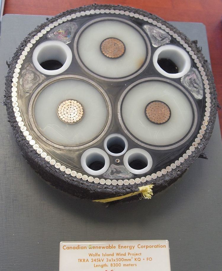
The purpose of submarine power cables is the transport of electric current at high voltage. The electric core is a concentric assembly of inner conductor, electric insulation and protective layers. The conductor is made from copper or aluminum wires, the latter material having a small but increasing market share. Conductor sizes ≤ 1200 are most common, but sizes ≥ 2400 mm2 have been made occasionally. For voltages ≥ 12 kV the conductors are round. Three different types of electric insulation around the conductor are mainly used today. Cross-linked polyethylene (XLPE) is used up to 420 kV system voltage. It is produced by extrusion in insulation thickness of up to about 30 mm. 36 kV class cables have only 5.5 – 8 mm insulation thickness. Certain formulations of XLPE insulation can also be used for DC. Low-pressure oil-filled cables have an insulation lapped from paper strips. The entire cable core is impregnated with a low-viscosity insulation fluid (mineral oil or synthetic). A central oil channel in the conductor facilitates oil flow when the cable gets warm. Rarely used in submarine cables due to oil pollution risk at cable damage. Is used up to 525 kV. Mass-impregnated cables have also a paper-lapped insulation but the impregnation compound is highly viscous and does not exit when the cable is damaged. MI insulation can be used for massive HVDC cables up to 525 kV. Cables ≥ 52 kV are equipped with an extruded lead sheath to prevent water intrusion. No other materials have been accepted so far. The lead alloy is extruded onto the insulation in long lengths (over 50 km is possible). In this stage the product is called cable core. In single-core cables the core is surrounded by a concentric armoring. In thre-core cables, three cable cores are laid-up in a spiral configuration before the armoring is applied. The armouring consists most often of steel wires, soaked in bitumen for corrosion protection. Since the alternating magnetic field in ac cables causes losses in the armoring those cables are sometimes equipped with non-magnetic metallic materials (stainless steel, copper, brass). Modern three-core cables, e.g. for the interconnection of offshore wind turbines) carry often optical fibers for data transmission or temperature measurement.
Selection between AC and DC
Most power systems use alternating current (AC). This is due mostly to the ease with which AC voltages may be stepped up and down, by means of a transformer. When the voltage is stepped up, current through the line is reduced, and since resistive losses in the line are proportional to the square of the current, stepping up the voltage significantly reduces the resistive line losses. The lack of a similarly simple and efficient system to perform the same function for DC made DC systems impractical in the late 19th and early 20th centuries. (Available devices, such as the rotary converter, were less efficient and required considerably more maintenance.) As technology improved, it became practical to step DC voltages up or down, though even today the process is much more complex than for AC systems. A DC voltage converter often consists of an inverter - essentially a high-power oscillator - to convert the DC to AC, a transformer to do the actual voltage stepping, and then a rectifier and filter stage to convert the AC back to DC.
DC switch gear is larger and more expensive to produce, since arc suppression is more difficult. When a switch or fuse first opens, current will continue to flow in an arc across the contacts. Once the contacts get far enough apart, the arc will extinguish because the electric field strength (volts per meter) is insufficient to sustain it. In AC circuits, current drops to zero twice during each AC cycle, at which time the arc extinguishes. If the distance between the contacts is still relatively small, the voltage will re-initiate an arc. Since DC is constant and these zero-crossing events do not occur, a DC switch must be designed to interrupt the full rated voltage and current, leading to larger and more expensive switching equipment. The voltage required to re-initiate an extinguished arc is much greater than the voltage required to sustain an arc.
DC power transmission does have some advantages over AC power transmission. AC transmission lines need to be designed to handle the peak voltage of the AC sine wave. However, since AC is a sine wave, the effective power that can be transmitted through the line is related to the root mean squared (RMS) value of the voltage, which for a sine wave is only
AC power transmission also suffers from reactive losses, due to the natural capacitance and inductive properties of wire. DC transmission lines do not suffer reactive losses. The only losses in a DC transmission line are the resistive losses, which are present in AC lines as well.
For an overall power transmission system, this means that for a given amount of power, AC requires more expensive wire, insulators, and towers but less expensive equipment like transformers and switch gear on either end of the line. For shorter distances, the cost of the equipment outweighs the savings in the cost of the transmission line. Over longer distances, the cost differential in the line starts to become more significant, which makes high-voltage direct current (HVDC) economically advantageous.
For underwater transmission systems, the line losses due to capacitance are much greater, which makes HVDC economically advantageous at a much shorter distance than on land.
Alternating current cables
Alternating-current (AC) submarine cable systems for transmitting lower amounts of three-phase electric power can be constructed with three-core cables in which all three insulated conductors are placed into a single underwater cable. Most offshore-to-shore wind-farm cables are constructed this way.
For larger amounts of transmitted power, the AC systems are composed of three separate single-core underwater cables, each containing just one insulated conductor and carrying one phase of the three phase electric current. A fourth identical cable is often added in parallel with the other three, simply as a spare in case one of the three primary cables is damaged and needs to be replaced. This damage can happen, for example, from a ship's anchor carelessly dropped onto it. The fourth cable can substitute for any one of the other three, given the proper electrical switching system.