
 | ||
Seismic retrofitting is the modification of existing structures to make them more resistant to seismic activity, ground motion, or soil failure due to earthquakes. With better understanding of seismic demand on structures and with our recent experiences with large earthquakes near urban centers, the need of seismic retrofitting is well acknowledged. Prior to the introduction of modern seismic codes in the late 1960s for developed countries (US, Japan etc.) and late 1970s for many other parts of the world (Turkey, China etc.), many structures were designed without adequate detailing and reinforcement for seismic protection. In view of the imminent problem, various research work has been carried out. State-of-the-art technical guidelines for seismic assessment, retrofit and rehabilitation have been published around the world – such as the ASCE-SEI 41 and the New Zealand Society for Earthquake Engineering (NZSEE)'s guidelines. These codes must be regularly updated; the 1994 Northridge earthquake brought to light the brittleness of welded steel frames, for example.
Contents
- Strategies
- Performance objectives
- Techniques
- External post tensioning
- Base isolators
- Supplementary dampers
- Tuned mass dampers
- Slosh tank
- Active control system
- Adhoc addition of structural supportreinforcement
- Connections between buildings and their expansion additions
- Exterior concrete columns
- Infill shear trusses
- Massive exterior structure
- Soft story failure
- Beam column joint connections
- Shear failure within floor diaphragm
- Sliding off foundation and cripple wall failure
- Multiple piers in shallow pits
- Reinforced concrete column burst
- Reinforced concrete wall burst
- Brick wall resin and glass fiber reinforcement
- Lift
- Soil
- Utility pipes and cables risks
- Tunnels
- Underwater tubes
- BART tube
- Bridge retrofit
- Expansion rockers
- Deck rigidity
- Lattice girders beams and ties
- Hot rivets
- Fill and overpass
- Viaducts
- Residential retrofit
- Wood frame structure
- Reinforced and unreinforced masonry
- References
The retrofit techniques outlined here are also applicable for other natural hazards such as tropical cyclones, tornadoes, and severe winds from thunderstorms. Whilst current practice of seismic retrofitting is predominantly concerned with structural improvements to reduce the seismic hazard of using the structures, it is similarly essential to reduce the hazards and losses from non-structural elements. It is also important to keep in mind that there is no such thing as an earthquake-proof structure, although seismic performance can be greatly enhanced through proper initial design or subsequent modifications.
Strategies
Seismic retrofit (or rehabilitation) strategies have been developed in the past few decades following the introduction of new seismic provisions and the availability of advanced materials (e.g. fiber-reinforced polymers (FRP), fiber reinforced concrete and high strength steel). Retrofit strategies are different from retrofit techniques, where the former is the basic approach to achieve an overall retrofit performance objective, such as increasing strength, increasing deformability, reducing deformation demands while the latter is the technical methods to achieve that strategy, for example FRP jacketing.
Performance objectives
In the past, seismic retrofit was primarily applied to achieve public safety, with engineering solutions limited by economic and political considerations. However, with the development of Performance based earthquake engineering (PBEE), several levels of performance objectives are gradually recognised:
Techniques
Common seismic retrofitting techniques fall into several categories:
External post-tensioning
The use of external post-tensioning for new structural systems have been developed in the past decade. Under the PRESS (Precast Seismic Structural Systems), a large-scale U.S./Japan joint research program, unbonded post-tensioning high strength steel tendons have been used to achieve a moment-resisting system that has self-centering capacity. An extension of the same idea for seismic retrofitting has been experimentally tested for seismic retrofit of California bridges under a Caltrans research project and for seismic retrofit of non-ductile reinforced concrete frames. Pre-stressing can increase the capacity of structural elements such as beam, column and beam-column joints. It should be noted that external pre-stressing has been used for structural upgrade for gravity/live loading since the 1970s.
Base isolators
Base isolation is a collection of structural elements of a building that should substantially decouple the building's structure from the shaking ground thus protecting the building's integrity and enhancing its seismic performance. This earthquake engineering technology, which is a kind of seismic vibration control, can be applied both to a newly designed building and to seismic upgrading of existing structures. Normally, excavations are made around the building and the building is separated from the foundations. Steel or reinforced concrete beams replace the connections to the foundations, while under these, the isolating pads, or base isolators, replace the material removed. While the base isolation tends to restrict transmission of the ground motion to the building, it also keeps the building positioned properly over the foundation. Careful attention to detail is required where the building interfaces with the ground, especially at entrances, stairways and ramps, to ensure sufficient relative motion of those structural elements.
Supplementary dampers
Supplementary dampers absorb the energy of motion and convert it to heat, thus "damping" resonant effects in structures that are rigidly attached to the ground. In addition to adding energy dissipation capacity to the structure, supplementary damping can reduce the displacement and acceleration demand within the structures. In some cases, the threat of damage does not come from the initial shock itself, but rather from the periodic resonant motion of the structure that repeated ground motion induces. In the practical sense, supplementary dampers act similarly to Shock absorbers used in automotive suspensions.
Tuned mass dampers
Tuned mass dampers (TMD) employ movable weights on some sort of springs. These are typically employed to reduce wind sway in very tall, light buildings. Similar designs may be employed to impart earthquake resistance in eight to ten story buildings that are prone to destructive earthquake induced resonances.
Slosh tank
A slosh tank is a large tank of fluid placed on an upper floor. During a seismic event, the fluid in this tank will slosh back and forth, but is directed by baffles – partitions that prevent the tank itself becoming resonant; through its mass the water may change or counter the resonant period of the building. Additional kinetic energy can be converted to heat by the baffles and is dissipated through the water – any temperature rise will be insignificant. One Rincon Hill in San Francisco is a recent skyscraper with a rooftop slosh tank.
Active control system
Very tall buildings ("skyscrapers"), when built using modern lightweight materials, might sway uncomfortably (but not dangerously) in certain wind conditions. A solution to this problem is to include at some upper story a large mass, constrained, but free to move within a limited range, and moving on some sort of bearing system such as an air cushion or hydraulic film. Hydraulic pistons, powered by electric pumps and accumulators, are actively driven to counter the wind forces and natural resonances. These may also, if properly designed, be effective in controlling excessive motion – with or without applied power – in an earthquake. In general, though, modern steel frame high rise buildings are not as subject to dangerous motion as are medium rise (eight to ten story) buildings, as the resonant period of a tall and massive building is longer than the approximately one second shocks applied by an earthquake.
Adhoc addition of structural support/reinforcement
The most common form of seismic retrofit to lower buildings is adding strength to the existing structure to resist seismic forces. The strengthening may be limited to connections between existing building elements or it may involve adding primary resisting elements such as walls or frames, particularly in the lower stories.
Connections between buildings and their expansion additions
Frequently, building additions will not be strongly connected to the existing structure, but simply placed adjacent to it, with only minor continuity in flooring, siding, and roofing. As a result, the addition may have a different resonant period than the original structure, and they may easily detach from one another. The relative motion will then cause the two parts to collide, causing severe structural damage. Seismic modification will either tie the two building components rigidly together so that they behave as a single mass or it will employ dampers to expend the energy from relative motion, with appropriate allowance for this motion, such as increased spacing and sliding bridges between sections.
Exterior concrete columns
Historic buildings, made of unreinforced masonry, may have culturally important interior detailing or murals that should not be disturbed. In this case, the solution may be to add a number of steel, reinforced concrete, or poststressed concrete columns to the exterior. Careful attention must be paid to the connections with other members such as footings, top plates, and roof trusses.
Infill shear trusses
Shown here is an exterior shear reinforcement of a conventional reinforced concrete dormitory building. In this case, there was sufficient vertical strength in the building columns and sufficient shear strength in the lower stories that only limited shear reinforcement was required to make it earthquake resistant for this location near the Hayward fault.
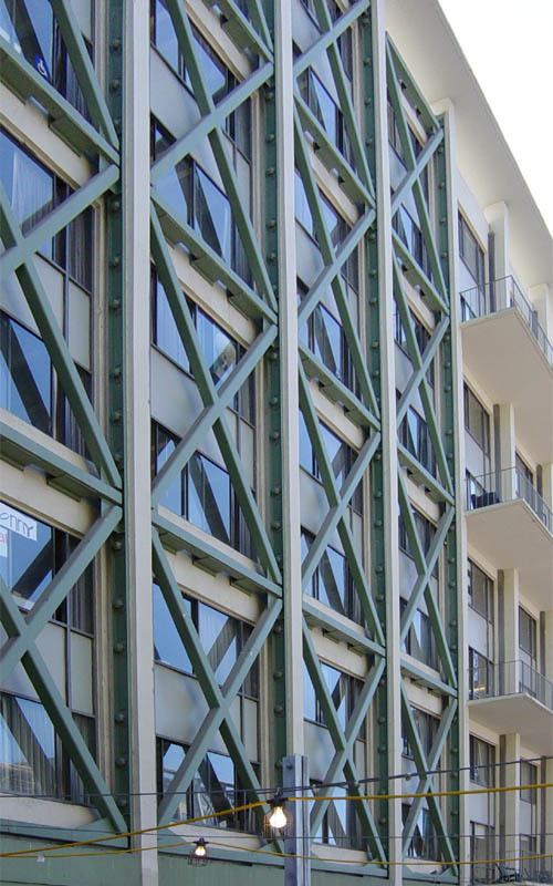
Massive exterior structure
In other circumstances, far greater reinforcement is required. In the structure shown at right — a parking garage over shops — the placement, detailing, and painting of the reinforcement becomes itself an architectural embellishment.
Soft-story failure
This collapse mode is known as soft story collapse. In many buildings the ground level is designed for different uses than the upper levels. Low rise residential structures may be built over a parking garage which have large doors on one side. Hotels may have a tall ground floors to allow for a grand entrance or ballrooms. Office buildings may have stores in the ground floor which desire continuous windows for display.
Traditional seismic design assumes that the lower stories of a building are stronger than the upper stories and where this is not the case—if the lower story is less strong than the upper structure—the structure will not respond to earthquakes in the expected fashion. Using modern design methods, it is possible to take a weak story into account. Several failures of this type in one large apartment complex caused most of the fatalities in the 1994 Northridge earthquake.
Typically, where this type of problem is found, the weak story is reinforced to make it stronger than the floors above by adding shear walls or moment frames. Moment frames consisting of inverted U bents are useful in preserving lower story garage access, while a lower cost solution may be to use shear walls or trusses in several locations, which partially reduce the usefulness for automobile parking but still allow the space to be used for other storage.
Beam-column joint connections
Beam-column joint connections are a common structural weakness in dealing with seismic retrofitting. Prior to the introduction of modern seismic codes in early 1970s, beam-column joints were typically non-engineered or designed. Laboratory testings have confirmed the seismic vulnerability of these poorly detailed and under-designed connections. Failure of beam-column joint connections can typically lead to catastrophic collapse of a frame-building, as often observed in recent earthquakes
For reinforced concrete beam-column joints – various retrofit solutions have been proposed and tested in the past 20 years. Philosophically, the various seismic retrofit strategies discussed above can be implemented for reinforced concrete joints. Concrete or steel jacketing have been a popular retrofit technique until the advent of composite materials such as Carbon fiber-reinforced polymer (FRP). Composite materials such as carbon FRP and aramic FRP have been extensively tested for use in seismic retrofit with some success. One novel technique includes the use of selective weakening of the beam and added external post-tensioning to the joint in order to achieve flexural hinging in the beam, which is more desirable in terms of seismic design.
Widespread weld failures at beam-column joints of low-to-medium rise steel buildings during the Northridge 1994 earthquake for example, have shown the structural defiencies of these 'modern-designed' post-1970s welded moment-resisting connections. A subsequent SAC research project [4] has documented, tested and proposed several retrofit solutions for these welded steel moment-resisting connections. Various retrofit solutions have been developed for these welded joints – such as a) weld strengthening and b) addition of steel haunch or 'dog-bone' shape flange.
Following the Northridge earthquake, a number of steel moment -frame buildings were found to have experienced brittle fractures of beam to column connections. Discovery of these unanticipated brittle fractures of framing connections was alarming to engineers and the building industry. Starting in the 1960s, engineers began to regard welded steel moment-frame buildings as being among the most ductile systems contained in the building code. Many engineers believed that steel moment-frame buildings were essentially invulnerable to earthquake induced damage and thought that should damage occur, it would be limited to ductile yielding of members and connections. Observation of damage sustained by buildings in the 1994 Northridge earthquake indicated that contrary to the intended behavior, in many cases, brittle fractures initiated within the connections at very low levels of plastic demand. In September, 1994, The SAC joint Venture, AISC, AISI, and NIST jointly convened an international workshop in Los Angeles to coordinate the efforts of various participants and to lay the foundation for systematic investigation and resolution of the problem. In September 1995 the SAC Joint Venture entered into a contractual agreement with FEMA to conduct Phase II of the SAC Steel project. Under Phase II, SAC continued its extensive problem-focused study of the performance of moment resisting steel frames and connections of various configurations, with the ultimate goal of developing seismic design criteria for steel construction. As a result of these studies it is now known that the typical moment-resisting connection detail employed in steel moment frame construction prior to the 1994 Northridge earthquake had a number of features that rendered it inherently susceptible to brittle fracture.
Shear failure within floor diaphragm
Floors in wooden buildings are usually constructed upon relatively deep spans of wood, called joists, covered with a diagonal wood planking or plywood to form a subfloor upon which the finish floor surface is laid. In many structures these are all aligned in the same direction. To prevent the beams from tipping over onto their side, blocking is used at each end, and for additional stiffness, blocking or diagonal wood or metal bracing may be placed between beams at one or more points in their spans. At the outer edge it is typical to use a single depth of blocking and a perimeter beam overall.
If the blocking or nailing is inadequate, each beam can be laid flat by the shear forces applied to the building. In this position they lack most of their original strength and the structure may further collapse. As part of a retrofit the blocking may be doubled, especially at the outer edges of the building. It may be appropriate to add additional nails between the sill plate of the perimeter wall erected upon the floor diaphragm, although this will require exposing the sill plate by removing interior plaster or exterior siding. As the sill plate may be quite old and dry and substantial nails must be used, it may be necessary to pre-drill a hole for the nail in the old wood to avoid splitting. When the wall is opened for this purpose it may also be appropriate to tie vertical wall elements into the foundation using specialty connectors and bolts glued with epoxy cement into holes drilled in the foundation.
Sliding off foundation and "cripple wall" failure
Single or two story wood-frame domestic structures built on a perimeter or slab foundation are relatively safe in an earthquake, but in many structures built before 1950 the sill plate that sits between the concrete foundation and the floor diaphragm (perimeter foundation) or studwall (slab foundation) may not be sufficiently bolted in. Additionally, older attachments (without substantial corrosion-proofing) may have corroded to a point of weakness. A sideways shock can slide the building entirely off of the foundations or slab.
Often such buildings, especially if constructed on a moderate slope, are erected on a platform connected to a perimeter foundation through low stud-walls called "cripple wall" or pin-up. This low wall structure itself may fail in shear or in its connections to itself at the corners, leading to the building moving diagonally and collapsing the low walls. The likelihood of failure of the pin-up can be reduced by ensuring that the corners are well reinforced in shear and that the shear panels are well connected to each other through the corner posts. This requires structural grade sheet plywood, often treated for rot resistance. This grade of plywood is made without interior unfilled knots and with more, thinner layers than common plywood. New buildings designed to resist earthquakes will typically use OSB (oriented strand board), sometimes with metal joins between panels, and with well attached stucco covering to enhance its performance. In many modern tract homes, especially those built upon expansive (clay) soil the building is constructed upon a single and relatively thick monolithic slab, kept in one piece by high tensile rods that are stressed after the slab has set. This poststressing places the concrete under compression – a condition under which it is extremely strong in bending and so will not crack under adverse soil conditions.
Multiple piers in shallow pits
Some older low-cost structures are elevated on tapered concrete pylons set into shallow pits, a method frequently used to attach outdoor decks to existing buildings. This is seen in conditions of damp soil, especially in tropical conditions, as it leaves a dry ventilated space under the house, and in far northern conditions of permafrost (frozen mud) as it keeps the building's warmth from destabilizing the ground beneath. During an earthquake, the pylons may tip, spilling the building to the ground. This can be overcome by using deep-bored holes to contain cast-in-place reinforced pylons, which are then secured to the floor panel at the corners of the building. Another technique is to add sufficient diagonal bracing or sections of concrete shear wall between pylons.
Reinforced concrete column burst
Reinforced concrete columns typically contain large diameter vertical rebar (reinforcing bars) arranged in a ring, surrounded by lighter-gauge hoops of rebar. Upon analysis of failures due to earthquakes, it has been realized that the weakness was not in the vertical bars, but rather in inadequate strength and quantity of hoops. Once the integrity of the hoops is breached, the vertical rebar can flex outward, stressing the central column of concrete. The concrete then simply crumbles into small pieces, now unconstrained by the surrounding rebar. In new construction a greater amount of hoop-like structures are used.
One simple retrofit is to surround the column with a jacket of steel plates formed and welded into a single cylinder. The space between the jacket and the column is then filled with concrete, a process called grouting. Where soil or structure conditions require such additional modification, additional pilings may be driven near the column base and concrete pads linking the pilings to the pylon are fabricated at or below ground level. In the example shown not all columns needed to be modified to gain sufficient seismic resistance for the conditions expected. (This location is about a mile from the Hayward Fault Zone.)
Reinforced concrete wall burst
Concrete walls are often used at the transition between elevated road fill and overpass structures. The wall is used both to retain the soil and so enable the use of a shorter span and also to transfer the weight of the span directly downward to footings in undisturbed soil. If these walls are inadequate they may crumble under the stress of an earthquake's induced ground motion.
One form of retrofit is to drill numerous holes into the surface of the wall, and secure short L-shaped sections of rebar to the surface of each hole with epoxy adhesive. Additional vertical and horizontal rebar is then secured to the new elements, a form is erected, and an additional layer of concrete is poured. This modification may be combined with additional footings in excavated trenches and additional support ledgers and tie-backs to retain the span on the bounding walls.
Brick wall resin and glass fiber reinforcement
Brick building structures have been reinforced with coatings of glass fiber and appropriate resin (epoxy or polyester). In lower floors these may be applied over entire exposed surfaces, while in upper floors this may be confined to narrow areas around window and door openings. This application provides tensile strength that stiffens the wall against bending away from the side with the application. The efficient protection of an entire building requires extensive analysis and engineering to determine the appropriate locations to be treated.
Lift
Where moist or poorly consolidated alluvial soil interfaces in a "beach like" structure against underlying firm material, seismic waves traveling through the alluvium can be amplified, just as are water waves against a sloping beach. In these special conditions, vertical accelerations up to twice the force of gravity have been measured. If a building is not secured to a well-embedded foundation it is possible for the building to be thrust from (or with) its foundations into the air, usually with severe damage upon landing. Even if it is well-founded, higher portions such as upper stories or roof structures or attached structures such as canopies and porches may become detached from the primary structure.
Good practices in modern, earthquake-resistant structures dictate that there be good vertical connections throughout every component of the building, from undisturbed or engineered earth to foundation to sill plate to vertical studs to plate cap through each floor and continuing to the roof structure. Above the foundation and sill plate the connections are typically made using steel strap or sheet stampings, nailed to wood members using special hardened high-shear strength nails, and heavy angle stampings secured with through bolts, using large washers to prevent pull-through. Where inadequate bolts are provided between the sill plates and a foundation in existing construction (or are not trusted due to possible corrosion), special clamp plates may be added, each of which is secured to the foundation using expansion bolts inserted into holes drilled in an exposed face of concrete. Other members must then be secured to the sill plates with additional fittings.
Soil
One of the most difficult retrofits is that required to prevent damage due to soil failure. Soil failure can occur on a slope, a slope failure or landslide, or in a flat area due to liquefaction of water-saturated sand and/or mud. Generally, deep pilings must be driven into stable soil (typically hard mud or sand) or to underlying bedrock or the slope must be stabilized. For buildings built atop previous landslides the practicality of retrofit may be limited by economic factors, as it is not practical to stabilize a large, deep landslide. The likelihood of landslide or soil failure may also depend upon seasonal factors, as the soil may be more stable at the beginning of a wet season than at the beginning of the dry season. Such a "two season" Mediterranean climate is seen throughout California.
In some cases, the best that can be done is to reduce the entrance of water runoff from higher, stable elevations by capturing and bypassing through channels or pipes, and to drain water infiltrated directly and from subsurface springs by inserting horizontal perforated tubes. There are numerous locations in California where extensive developments have been built atop archaic landslides, which have not moved in historic times but which (if both water-saturated and shaken by an earthquake) have a high probability of moving en masse, carrying entire sections of suburban development to new locations. While the most modern of house structures (well tied to monolithic concrete foundation slabs reinforced with post tensioning cables) may survive such movement largely intact, the building will no longer be in its proper location.
Utility pipes and cables: risks
Natural gas and propane supply pipes to structures often prove especially dangerous during and after earthquakes. Should a building move from its foundation or fall due to cripple wall collapse, the ductile iron pipes transporting the gas within the structure may be broken, typically at the location of threaded joints. The gas may then still be provided to the pressure regulator from higher pressure lines and so continue to flow in substantial quantities; it may then be ignited by a nearby source such as a lit pilot light or arcing electrical connection.
There are two primary methods of automatically restraining the flow of gas after an earthquake, installed on the low pressure side of the regulator, and usually downstream of the gas meter.
It appears that the most secure configuration would be to use one of each of these devices in series.
Tunnels
Unless the tunnel penetrates a fault likely to slip, the greatest danger to tunnels is a landslide blocking an entrance. Additional protection around the entrance may be applied to divert any falling material (similar as is done to divert snow avalanches) or the slope above the tunnel may be stabilized in some way. Where only small- to medium-sized rocks and boulders are expected to fall, the entire slope may be covered with wire mesh, pinned down to the slope with metal rods. This is also a common modification to highway cuts where appropriate conditions exist.
Underwater tubes
The safety of underwater tubes is highly dependent upon the soil conditions through which the tunnel was constructed, the materials and reinforcements used, and the maximum predicted earthquake expected, and other factors, some of which may remain unknown under current knowledge.
BART tube
For current BART information concerning various seismic retrofits see [5].A tube of particular structural, seismic, economic, and political interest is the BART (Bay Area Rapid Transit) transbay tube. This tube was constructed at the bottom of San Francisco Bay through an innovative process. Rather than pushing a shield through the soft bay mud, the tube was constructed on land in sections. Each section consisted of two inner train tunnels of circular cross section, a central access tunnel of rectangular cross section, and an outer oval shell encompassing the three inner tubes. The intervening space was filled with concrete. At the bottom of the bay a trench was excavated and a flat bed of crushed stone prepared to receive the tube sections. The sections were then floated into place and sunk, then joined with bolted connections to previously-placed sections. An overfill was then placed atop the tube to hold it down. Once completed from San Francisco to Oakland, the tracks and electrical components were installed. The predicted response of the tube during a major earthquake was likened to be as that of a string of (cooked) spaghetti in a bowl of gelatin dessert. To avoid overstressing the tube due to differential movements at each end, a sliding slip joint was included at the San Francisco terminus under the landmark Ferry Building.
The engineers of the construction consortium PBTB (Parsons Brinckerhoff-Tudor-Bechtel) used the best estimates of ground motion available at the time, now known to be insufficient given modern computational analysis methods and geotechnical knowledge. Unexpected settlement of the tube has reduced the amount of slip that can be accommodated without failure. These factors have resulted in the slip joint being designed too short to ensure survival of the tube under possible (perhaps even likely) large earthquakes in the region. To correct this deficiency the slip joint must be extended to allow for additional movement, a modification expected to be both expensive and technically and logistically difficult. Other retrofits to the BART tube include vibratory consolidation of the tube's overfill to avoid potential liquefying of the overfill, which has now been completed. (Should the overfill fail there is a danger of portions of the tube rising from the bottom, an event which could potentially cause failure of the section connections.)
Bridge retrofit
Bridges have several failure modes.
Expansion rockers
Many short bridge spans are statically anchored at one end and attached to rockers at the other. This rocker gives vertical and transverse support while allowing the bridge span to expand and contract with temperature changes. The change in the length of the span is accommodated over a gap in the roadway by comb-like expansion joints. During severe ground motion, the rockers may jump from their tracks or be moved beyond their design limits, causing the bridge to unship from its resting point and then either become misaligned or fail completely. Motion can be constrained by adding ductile or high-strength steel restraints that are friction-clamped to beams and designed to slide under extreme stress while still limiting the motion relative to the anchorage.
Deck rigidity
Suspension bridges may respond to earthquakes with a side-to-side motion exceeding that which was designed for wind gust response. Such motion can cause fragmentation of the road surface, damage to bearings, and plastic deformation or breakage of components. Devices such as hydraulic dampers or clamped sliding connections and additional diagonal reenforcement may be added.
Lattice girders, beams, and ties
Lattice girders consist of two "I"-beams connected with a criss-cross lattice of flat strap or angle stock. These can be greatly strengthened by replacing the open lattice with plate members. This is usually done in concert with the replacement of hot rivets with bolts.
Hot rivets
Many older structures were fabricated by inserting red-hot rivets into pre-drilled holes; the soft rivets are then peened using an air hammer on one side and a bucking bar on the head end. As these cool slowly, they are left in an annealed (soft) condition, while the plate, having been hot rolled and quenched during manufacture, remains relatively hard. Under extreme stress the hard plates can shear the soft rivets, resulting in failure of the joint.
The solution is to burn out each rivet with an oxygen torch. The hole is then prepared to a precise diameter with a reamer. A special locator bolt, consisting of a head, a shaft matching the reamed hole, and a threaded end is inserted and retained with a nut, then tightened with a wrench. As the bolt has been formed from an appropriate high-strength alloy and has also been heat-treated, it is not subject to either the plastic shear failure typical of hot rivets nor the brittle fracture of ordinary bolts. Any partial failure will be in the plastic flow of the metal secured by the bolt; with proper engineering any such failure should be non-catastrophic.
Fill and overpass
Elevated roadways are typically built on sections of elevated earth fill connected with bridge-like segments, often supported with vertical columns. If the soil fails where a bridge terminates, the bridge may become disconnected from the rest of the roadway and break away. The retrofit for this is to add additional reinforcement to any supporting wall, or to add deep caissons adjacent to the edge at each end and connect them with a supporting beam under the bridge.
Another failure occurs when the fill at each end moves (through resonant effects) in bulk, in opposite directions. If there is an insufficient founding shelf for the overpass, then it may fall. Additional shelf and ductile stays may be added to attach the overpass to the footings at one or both ends. The stays, rather than being fixed to the beams, may instead be clamped to them. Under moderate loading, these keep the overpass centered in the gap so that it is less likely to slide off its founding shelf at one end. The ability for the fixed ends to slide, rather than break, will prevent the complete drop of the structure if it should fail to remain on the footings.
Viaducts
Large sections of roadway may consist entirely of viaduct, sections with no connection to the earth other than through vertical columns. When concrete columns are used, the detailing is critical. Typical failure may be in the toppling of a row of columns due either to soil connection failure or to insufficient cylindrical wrapping with rebar. Both failures were seen in the 1995 Great Hanshin earthquake in Kobe, Japan, where an entire viaduct, centrally supported by a single row of large columns, was laid down to one side. Such columns are reinforced by excavating to the foundation pad, driving additional pilings, and adding a new, larger pad, well connected with rebar alongside or into the column. A column with insufficient wrapping bar, which is prone to burst and then hinge at the bursting point, may be completely encased in a circular or elliptical jacket of welded steel sheet and grouted as described above.
Sometimes viaducts may fail in the connections between components. This was seen in the failure of the Cypress Freeway in Oakland, California, during the Loma Prieta earthquake. This viaduct was a two-level structure, and the upper portions of the columns were not well connected to the lower portions that supported the lower level; this caused the upper deck to collapse upon the lower deck. Weak connections such as these require additional external jacketing – either through external steel components or by a complete jacket of reinforced concrete, often using stub connections that are glued (using epoxy adhesive) into numerous drilled holes. These stubs are then connected to additional wrappings, external forms (which may be temporary or permanent) are erected, and additional concrete is poured into the space. Large connected structures similar to the Cypress Viaduct must also be properly analyzed in their entirety using dynamic computer simulations.
Residential retrofit
Side-to-side forces cause most earthquake damage. Bolting of the mudsill to the foundation and application of plywood to cripple walls are a few basic retrofit techniques which homeowners may apply to wood-framed residential structures to mitigate the effects of seismic activity. The City of San Leandro created guidelines for these procedures, as outlined in the following pamphlet. Public awareness and initiative are critical to the retrofit and preservation of existing building stock, and such efforts as those of the Association of Bay Area Governments are instrumental in providing informational resources to seismically active communities.
Wood frame structure
Most houses in North America are wood-framed structures. Wood is one of the best materials for earthquake-resistant construction since it is lightweight and more flexible than masonry. It is easy to work with and less expensive than steel, masonry, or concrete. In older homes the most significant weaknesses are the connection from the wood-framed walls to the foundation and the relatively weak "cripple-walls." (Cripple walls are the short wood walls that extend from the top of the foundation to the lowest floor level in houses that have raised floors.) Adding connections from the base of the wood-framed structure to the foundation is almost always an important part of a seismic retrofit. Bracing the cripple-walls to resist side-to-side forces is essential in houses with cripple walls; bracing is usually done with plywood. Oriented strand board (OSB) does not perform as consistently as plywood, and is not the favored choice of retrofit designers or installers.
Retrofit methods in older woodframe structures may consist of the following, and other methods not described here.
Wooden framing is efficient when combined with masonry, if the structure is properly designed. In Turkey, the traditional houses (bagdadi) are made with this technology. In El Salvador, wood and bamboo are used for residential construction.
Reinforced and unreinforced masonry
In many parts of developing countries such as Pakistan, Iran and China, unreinforced or in some cases reinforced masonry is the predominantly form of structures for rural residential and dwelling. Masonry was also a common construction form in the early part of the 20th century, which implies that a substantial number of these at-risk masonry structures would have significant heritage value. Masonry walls that are not reinforced are especially hazardous. Such structures may be more appropriate for replacement than retrofit, but if the walls are the principal load bearing elements in structures of modest size they may be appropriately reinforced. It is especially important that floor and ceiling beams be securely attached to the walls. Additional vertical supports in the form of steel or reinforced concrete may be added.
In the western United States, much of what is seen as masonry is actually brick or stone veneer. Current construction rules dictate the amount of tie–back required, which consist of metal straps secured to vertical structural elements. These straps extend into mortar courses, securing the veneer to the primary structure. Older structures may not secure this sufficiently for seismic safety. A weakly secured veneer in a house interior (sometimes used to face a fireplace from floor to ceiling) can be especially dangerous to occupants. Older masonry chimneys are also dangerous if they have substantial vertical extension above the roof. These are prone to breakage at the roofline and may fall into the house in a single large piece. For retrofit, additional supports may be added; however, it is extremely expensive to strengthen an existing masonry chimney to conform with contemporary design standards. It is best to simply remove the extension and replace it with lighter materials, with special metal flue replacing the flue tile and a wood structure replacing the masonry. This may be matched against existing brickwork by using very thin veneer (similar to a tile, but with the appearance of a brick).