
 | ||
Nondestructive testing or non-destructive testing (NDT) is a wide group of analysis techniques used in science and technology industry to evaluate the properties of a material, component or system without causing damage. The terms nondestructive examination (NDE), nondestructive inspection (NDI), and nondestructive evaluation (NDE) are also commonly used to describe this technology. Because NDT does not permanently alter the article being inspected, it is a highly valuable technique that can save both money and time in product evaluation, troubleshooting, and research. Common NDT methods include ultrasonic, magnetic-particle, liquid penetrant, radiographic, remote visual inspection (RVI), eddy-current testing, and low coherence interferometry. NDT is commonly used in forensic engineering, mechanical engineering, petroleum engineering, electrical engineering, civil engineering, systems engineering, aeronautical engineering, medicine, and art. Innovations in the field of nondestructive testing have had a profound impact on medical imaging, including on echocardiography, medical ultrasonography, and digital radiography.
Contents
- Methods
- Applications
- Weld verification
- Structural mechanics
- Radiography in medicine
- Notable events in early academic and industrial NDT
- Methods and techniques
- Personnel training qualification and certification
- Definitions
- Training
- Certification schemes
- Levels of certification
- Terminology
- Reliability and statistics
- References
Methods
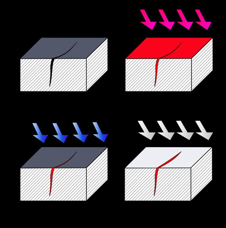
NDT methods may rely upon use of electromagnetic radiation, sound, and inherent properties of materials to examine samples. This includes some kinds of microscopy to examine external surfaces in detail, although sample preparation techniques for metallography, optical microscopy and electron microscopy are generally destructive as the surfaces must be made smooth through polishing or the sample must be electron transparent in thickness. The inside of a sample can be examined with penetrating radiation, such as X-rays, neutrons or terahertz radiation. Sound waves are utilized in the case of ultrasonic testing. Contrast between a defect and the bulk of the sample may be enhanced for visual examination by the unaided eye by using liquids to penetrate fatigue cracks. One method (liquid penetrant testing) involves using dyes, fluorescent or non-fluorescent, in fluids for non-magnetic materials, usually metals. Another commonly used NDT method used on ferrous materials involves the application of fine iron particles (either liquid or dry dust) that are applied to a part while it is in an externally magnetized state (magnetic-particle testing). The particles will be attracted to leakage fields within the test object, and form on the objects surface. Magnetic particle testing can reveal surface & some sub-surface defects within the part. Thermoelectric effect (or use of the Seebeck effect) uses thermal properties of an alloy to quickly and easily characterize many alloys. The chemical test, or chemical spot test method, utilizes application of sensitive chemicals that can indicate the presence of individual alloying elements. Electrochemical methods, such as electrochemical fatigue crack sensors, utilize the tendency of metal structural material to oxidize readily in order to detect progressive damage.
Analyzing and documenting a non-destructive failure mode can also be accomplished using a high-speed camera recording continuously (movie-loop) until the failure is detected. Detecting the failure can be accomplished using a sound detector or stress gauge which produces a signal to trigger the high-speed camera. These high-speed cameras have advanced recording modes to capture some non-destructive failures. After the failure the high-speed camera will stop recording. The capture images can be played back in slow motion showing precisely what happen before, during and after the non-destructive event, image by image.
Applications
NDT is used in a variety of settings that covers a wide range of industrial activity, with new NDT methods and applications, being continuously developed. Non-destructive testing methods are routinely applied in industries where a failure of a component would cause significant hazard or economic loss, such as in transportation, pressure vessels, building structures, piping, and hoisting equipment.
Weld verification
In manufacturing, welds are commonly used to join two or more metal parts. Because these connections may encounter loads and fatigue during product lifetime, there is a chance that they may fail if not created to proper specification. For example, the base metal must reach a certain temperature during the welding process, must cool at a specific rate, and must be welded with compatible materials or the joint may not be strong enough to hold the parts together, or cracks may form in the weld causing it to fail. The typical welding defects (lack of fusion of the weld to the base metal, cracks or porosity inside the weld, and variations in weld density) could cause a structure to break or a pipeline to rupture.
Welds may be tested using NDT techniques such as industrial radiography or industrial CT scanning using X-rays or gamma rays, ultrasonic testing, liquid penetrant testing, magnetic particle inspection or via eddy current. In a proper weld, these tests would indicate a lack of cracks in the radiograph, show clear passage of sound through the weld and back, or indicate a clear surface without penetrant captured in cracks.
Welding techniques may also be actively monitored with acoustic emission techniques before production to design the best set of parameters to use to properly join two materials. In the case of high stress or safety critical welds, weld monitoring will be employed to confirm the specified welding parameters (arc current, arc voltage, travel speed, heat input etc.) are being adhered to those stated in the welding procedure. This verifies the weld as correct to procedure prior to nondestructive evaluation and metallurgy tests.
Structural mechanics
Structure can be complex systems that undergo different loads during their lifetime, e.g. Lithium-ion batteries. Some complex structures, such as the turbo machinery in a liquid-fuel rocket, can also cost millions of dollars. Engineers will commonly model these structures as coupled second-order systems, approximating dynamic structure components with springs, masses, and dampers. The resulting sets of differential equations are then used to derive a transfer function that models the behavior of the system.
In NDT, the structure undergoes a dynamic input, such as the tap of a hammer or a controlled impulse. Key properties, such as displacement or acceleration at different points of the structure, are measured as the corresponding output. This output is recorded and compared to the corresponding output given by the transfer function and the known input. Differences may indicate an inappropriate model (which may alert engineers to unpredicted instabilities or performance outside of tolerances), failed components, or an inadequate control system.
Radiography in medicine
As a system, the human body is difficult to model as a complete transfer function. Elements of the body, however, such as bones or molecules, have a known response to certain radiographic inputs, such as x-rays or magnetic resonance. Coupled with the controlled introduction of a known element, such as digested barium, radiography can be used to image parts or functions of the body by measuring and interpreting the response to the radiographic input. In this manner, many bone fractures and diseases may be detected and localized in preparation for treatment. X-rays may also be used to examine the interior of mechanical systems in manufacturing using NDT techniques, as well.
Notable events in early academic and industrial NDT
(Basic Source for above: Hellier, 2001) Note the number of advancements made during the WWII era, a time when industrial quality control was growing in importance.
Methods and techniques
NDT is divided into various methods of nondestructive testing, each based on a particular scientific principle. These methods may be further subdivided into various techniques. The various methods and techniques, due to their particular natures, may lend themselves especially well to certain applications and be of little or no value at all in other applications. Therefore, choosing the right method and technique is an important part of the performance of NDT.
Personnel training, qualification and certification
Successful and consistent application of nondestructive testing techniques depends heavily on personnel training, experience and integrity. Personnel involved in application of industrial NDT methods and interpretation of results should be certified, and in some industrial sectors certification is enforced by law or by the applied codes and standards.
Definitions
The following definitions for qualification and certification are given in ISO 9712:
In US standards and codes, while a very similar definition of qualification is included in ASNT SNT-TC-1A, certification is simply defined as: "Written testimony of qualification".
In the aerospace sector, EN 4179:2009 contains the following definitions:
Training
Non-Destructive Testing (NDT) training is provided for people working in many industries. It is generally necessary that the candidate successfully completes a theoretical and practical training program, as well as have performed several hundred hours of practical application of the particular method they wish to be trained in. At this point, they may pass a certification examination. While online training has become more popular, many certifying bodies will require additional practical training.
Certification schemes
There are two approaches in personnel certification:
- Employer Based Certification: Under this concept the employer compiles their own Written Practice. The written practice defines the responsibilities of each level of certification, as implemented by the company, and describes the training, experience and examination requirements for each level of certification. In industrial sectors the written practices are usually based on recommended practice SNT-TC-1A of the American Society for Nondestructive Testing. ANSI standard CP-189 outlines requirements for any written practice that conforms to the standard. For aviation, space, and defense (ASD) applications NAS 410 sets further requirements for NDT personnel, and is published by AIA - Aerospace Industries Association, which is made up of US aerospace airframe and powerplant manufacturers. This is the basis document for EN 4179 and other (USA) NIST-recognized aerospace standards for the Qualification and Certification (employer-based) of Nondestructive Testing personnel. NAS 410 also sets the requirements also for "National NDT Boards", which allow and proscribe personal certification schemes. NAS 410 allows ASNT Certification as a portion of the qualifications needed for ASD certification.
- Personal Central Certification: The concept of central certification is that an NDT operator can obtain certification from a central certification authority, that is recognized by most employers, third parties and/or government authorities. Industrial standards for central certification schemes include ISO 9712, and ANSI/ASNT CP-106 (used for the ASNT ACCP scheme). Certification under these standards involves training, work experience under supervision and passing a written and practical examination set up by the independent certification authority. EN 473 was another central certification scheme, very similar to ISO 9712, which was withdrawn when CEN replaced it with EN ISO 9712 in 2012.
In the United States employer based schemes are the norm, however central certification schemes exist as well. The most notable is ASNT Level III (established in 1976-1977), which is organized by the American Society for Nondestructive Testing for Level 3 NDT personnel. NAVSEA 250-1500 is another US central certification scheme, specifically developed for use in the naval nuclear program.
Central certification is more widely used in the European Union, where certifications are issued by accredited bodies (independent organizations conforming to ISO 17024 and accredited by a national accreditation authority like UKAS). The Pressure Equipment Directive (97/23/EC) actually enforces central personnel certification for the initial testing of steam boilers and some categories of pressure vessels and piping. European Standards harmonized with this directive specify personnel certification to EN 473. Certifications issued by a national NDT society which is a member of the European Federation of NDT (EFNDT) are mutually acceptable by the other member societies under a multilateral recognition agreement.
Canada also implements an ISO 9712 central certification scheme, which is administered by Natural Resources Canada, a government department.
The aerospace sector worldwide sticks to employer based schemes. In America it is based mostly on AIA-NAS-410 and in the European Union on the equivalent and very similar standard EN 4179. However EN 4179:2009 includes an option for central qualification and certification by a National aerospace NDT board or NANDTB (paragraph 4.5.2).
Levels of certification
Most NDT personnel certification schemes listed above specify three "levels" of qualification and/or certification, usually designated as Level 1, Level 2 and Level 3 (although some codes specify Roman numerals, like Level II). The roles and responsibilities of personnel in each level are generally as follows (there are slight differences or variations between different codes and standards):
Terminology
The standard US terminology for Nondestructive testing is defined in standard ASTM E-1316. Some definitions may be different in European standard EN 1330.
Reliability and statistics
Probability of detection (POD) tests are a standard way to evaluate a nondestructive testing technique in a given set of circumstances, for example "What is the POD of lack of fusion flaws in pipe welds using manual ultrasonic testing?" The POD will usually increase with flaw size. A common error in POD tests is to assume that the percentage of flaws detected is the POD, whereas the percentage of flaws detected is merely the first step in the analysis. Since the number of flaws tested is necessarily a limited number (non-infinite), statistical methods must be used to determine the POD for all possible defects, beyond the limited number tested. Another common error in POD tests is to define the statistical sampling units (test items) as flaws, whereas a true sampling unit is an item that may or may not contain a flaw. Guidelines for correct application of statistical methods to POD tests can be found in ASTM E2862 Standard Practice for Probability of Detection Analysis for Hit/Miss Data and MIL-HDBK-1823A Nondestructive Evaluation System Reliability Assessment, from the U.S. Department of Defense Handbook.