
 | ||
Guided Wave testing (GWT) is one of latest methods in the field of non-destructive evaluation. The method employs mechanical stress waves that propagate along an elongated structure while guided by its boundaries. This allows the waves to travel a long distance with little loss in energy. Nowadays, GWT is widely used to inspect and screen many engineering structures, particularly for the inspection of metallic pipelines around the world. In some cases, hundreds of meters can be inspected from a single location. There are also some applications for inspecting rail tracks, rods and metal plate structures.
Contents
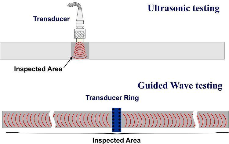
Although Guided wave testing is also commonly known as Guided Wave Ultrasonic Testing (GWUT) or Ultrasonic Guided Waves (UGWs) or Long Range Ultrasonic Testing (LRUT), it is fundamentally very different from conventional ultrasonic testing. Guided wave testing uses very low ultrasonic frequencies compared to those used in conventional UT, typically between 10~100 kHz. Higher frequencies can be used in some cases, but detection range is significantly reduced. In addition, the underlying physics of guided waves is more complex than bulk waves. Much of the theoretical background has been addressed in a separate article. In this article, the practical aspect of GWT will be discussed.
History
The study of guided waves propagating in a structure can be traced back to as early as the 1920s, mainly inspired by the field of seismology. Since then, there has been an increased effort on the analytical study of guided wave propagation in cylindrical structures. It was only in the early 1990s that guided wave testing was considered as a practical method for the non-destructive testing of engineering structures. Today, GWT is applied as an integrated health monitoring program in the oil, gas and chemical industries.
How it works (Pipeline Inspections)
Unlike conventional ultrasonics, there are an infinite number of guided wave modes that exist for a pipe geometry, and they can be generally grouped into three families, namely the torsional, longitudinal and flexural modes. The acoustic properties of these wave modes are a function of the pipe geometry, the material and the frequency. Predicting these properties of the wave modes often relies on heavy mathematical modeling which are typically presented in graphical plots called Dispersion curves.
In Guided Wave Testing of pipelines, an array of low frequency transducers is attached around the circumference of the pipe to generate an axially symmetric wave that propagates along the pipe in both the forward and backward directions of the transducer array. The Torsional wave mode is most commonly used, although there is limited use of the longitudinal mode. The equipment operates in a pulse-echo configuration where the array of transducers is used for both the excitation and detection of the signals.
At a location where there is a change of cross-section or a change in local stiffness of the pipe, an echo is generated. Based on the arrival time of the echoes, and the predicted speed of the wave mode at a particular frequency, the distance of a feature in relation to the position of the transducer array can be accurately calculated. GWT uses a system of distance amplitude curves (DAC) to correct for attenuation and amplitude drops when estimating the cross-section change (CSC) from a reflection at a certain distance. The DACs are usually calibrated against a series of echoes with known signal amplitude such as weld echoes.
Once the DAC levels are set, the signal amplitude correlates well to the CSC of a defect. GWT does not measure the remaining wall thickness directly, but it is possible to group the defect severity in several categories. One method of doing this is to exploit the mode conversion phenomenon of the excitation signal where some energy of the axially symmetric wave mode is converted to the flexural modes at a pipe feature. The amount of mode conversion provides an accurate estimate of the circumferential extent of the defect, and together with the CSC, operators could establish the severity category.
A typical result of GWT is displayed in an A-scan style with the reflection amplitude against the distance from the transducer array position. In the past few years, some advanced systems have started to offer C-scan type results where the orientation of each feature can be easily interpreted. This has shown to be extremely useful when inspecting large size pipelines.
Guided Wave Focusing
As well as incorporating C-scan type results, active focusing capacity can also be achieved by GWT utilising flexural wave modes. This gives two main advantages; firstly the signal to noise ratio (SNR) of a defect echo can be enhanced, secondly it can be used as an additional tool to help discriminate between ‘real’ and ‘false’ indications. However, there are disadvantages associated with this technique; firstly, the defect location must be known before the focusing can be applied, secondly, the separate data set required for the active focusing technique can also significantly reduce the time and cost efficiency of GWT.
Flexural wave modes have sinusoidal variation in their displacement pattern around the circumference, in integer values ranging from 1 to Infinity. Active focusing involves the transmission of multiple flexural wave modes, with time and amplitude corrections applied, in such a way that a circumferential node from each wave mode will arrive at the target position at the same time, the same circumferential position and with the same phase, causing constructive interference. At other circumferential positions the circumferential nodes of the flexural wave modes will arrive out of phase with each other and will interfere destructively. Adjusting the excitation conditions can rotate this focal spot around the pipes circumference. Comparing the response from different circumferential positions can allow the operator to more accurately predict the circumferential position and extent of a defect.
As previously mentioned, the focusing technique can also be used to help discriminate between ‘real’ and ‘false’ indications, a ‘false’ indication being a received signal that does not directly correspond to the position of a defect; such as those from reverberations or from incomplete cancellation of unwanted wave modes. If a ‘false’ indication is present in the A-scan data, it will also be re-represented in any C-scan type results as this type of processing uses the same original data. As active focusing involves a separate data collection, focusing at the position of a ‘false’ indication will give a negative result, whereas focusing on a ‘true’ indication will give a positive result. Therefore, the active focusing technique can help overcome the propensity of ‘false calls’ generated by guided wave testing systems.
Advantages
- Rapid screening for in-service degradation (Long range inspection) - potential to achieve hundreds of meters of inspection range.
- Detection of internal or external metal loss
- Reduction in costs of gaining access - insulated line with minimal insulation removal, corrosion under supports without need for lifting, inspection at elevated locations with minimal need for scaffolding, and inspection of road crossings and buried pipes.
- Data is fully recorded.
- Fully automated data collection protocols.
Disadvantages
- Interpretation of data is highly operator dependent.
- Difficult to find small pitting defects.
- Not very effective at inspecting areas close to accessories.
- Needs good procedure