
 | ||
In electronics, a linear regulator is a system used to maintain a steady voltage. The resistance of the regulator varies in accordance with the load resulting in a constant output voltage. The regulating device is made to act like a variable resistor, continuously adjusting a voltage divider network to maintain a constant output voltage and continually dissipating the difference between the input and regulated voltages as waste heat. By contrast, a switching regulator uses an active device that switches on and off to maintain an average value of output. Because the regulated voltage of a linear regulator must always be lower than input voltage, efficiency is limited and the input voltage must be high enough to always allow the active device to drop some voltage.
Contents
- Overview
- Shunt regulators
- Series regulators
- Simple shunt regulator
- Simple series regulator
- Fixed regulators
- Adjusting fixed regulators
- Variable regulators
- Protection
- Using a linear regulator
- References
Linear regulators may place the regulating device in parallel with the load (shunt regulator) or may place the regulating device between the source and the regulated load (a series regulator). Simple linear regulators may only contain a Zener diode and a series resistor; more complicated regulators include separate stages of voltage reference, error amplifier and power pass element. Because a linear voltage regulator is a common element of many devices, integrated circuit regulators are very common. Linear regulators may also be made up of assemblies of discrete solid-state or vacuum tube components.
Overview
The transistor (or other device) is used as one half of a potential divider to establish the regulated output voltage. The output voltage is compared to a reference voltage to produce a control signal to the transistor which will drive its gate or base. With negative feedback and good choice of compensation, the output voltage is kept reasonably constant. Linear regulators are often inefficient: since the transistor is acting like a resistor, it will waste electrical energy by converting it to heat. In fact, the power loss due to heating in the transistor is the current multiplied by the voltage difference between input and output voltage. The same function can often be performed much more efficiently by a switched-mode power supply, but a linear regulator may be preferred for light loads or where the desired output voltage approaches the source voltage. In these cases, the linear regulator may dissipate less power than a switcher. The linear regulator also has the advantage of not requiring magnetic devices (inductors or transformers) which can be relatively expensive or bulky, being often of simpler design, and being quieter. Some designs of linear regulators use only transistors, diodes and resistors, which are easier to fabricate into an integrated circuit, further reducing their weight, footprint on a PCB, and price.
All linear regulators require an input voltage at least some minimum amount higher than the desired output voltage. That minimum amount is called the dropout voltage. For example, a common regulator such as the 7805 has an output voltage of 5V, but can only maintain this if the input voltage remains above about 7V, before the output voltage begins sagging below the rated output. Its dropout voltage is therefore 7V − 5V = 2V. When the supply voltage is less than about 2V above the desired output voltage, as is the case in low-voltage microprocessor power supplies, so-called low dropout regulators (LDOs) must be used.
When the output regulated voltage must be higher than the available input voltage, no linear regulator will work (not even a Low dropout regulator). In this situation, something like a switched-mode power supply of the "boost" type or a charge pump must be used. Most linear regulators will continue to provide some output voltage approximately the dropout voltage below the input voltage for inputs below the nominal output voltage until the input voltage drops significantly.
Linear regulators exist in two basic forms: shunt regulators and series regulators. Most linear regulators have a maximum rated output current. This is generally limited by either power dissipation capability, or by the current carrying capability of the output transistor.
Shunt regulators
The shunt regulator works by providing a path from the supply voltage to ground through a variable resistance (the main transistor is in the "bottom half" of the voltage divider). The current through the shunt regulator is diverted away from the load and flows uselessly to ground, making this form usually less efficient than the series regulator. It is, however, simpler, sometimes consisting of just a voltage-reference diode, and is used in very low-powered circuits where the wasted current is too small to be of concern. This form is very common for voltage reference circuits. A shunt regulator can usually only sink (absorb) current.
Series regulators
Series regulators are the more common form; they are more efficient than shunt designs. The series regulator works by providing a path from the supply voltage to the load through a variable resistance, usually a transistor (in this role it is usually termed the series pass transistor); it is in the "top half" of the voltage divider - the bottom half being the load. The power dissipated by the regulating device is equal to the power supply output current times the voltage drop in the regulating device. For efficiency and reduced stress on the pass transistor, designs try to minimize the voltage drop but not all circuits regulate well once the input (unregulated) voltage comes close to the required output voltage; those that do are termed Low Dropout regulators, A series regulator can usually only source (supply) current, unlike shunt regulators.
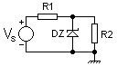
Simple shunt regulator
The image shows a simple shunt voltage regulator that operates by way of the Zener diode's action of maintaining a constant voltage across itself when the current through it is sufficient to take it into the Zener breakdown region. The resistor R1 supplies the Zener current
This regulator is used for very simple low-power applications where the currents involved are very small and the load is permanently connected across the Zener diode (such as voltage reference or voltage source circuits). Once R1 has been calculated, removing R2 will allow the full load current (plus the Zener current) through the diode and may exceed the diode's maximum current rating, thereby damaging it. The regulation of this circuit is also not very good because the Zener current (and hence the Zener voltage) will vary depending on
Simple series regulator
Adding an emitter follower stage to the simple shunt regulator forms a simple series voltage regulator and substantially improves the regulation of the circuit. Here, the load current IR2 is supplied by the transistor whose base is now connected to the Zener diode. Thus the transistor's base current (IB) forms the load current for the Zener diode and is much smaller than the current through R2. This regulator is classified as "series" because the regulating element, viz., the transistor, appears in series with the load. R1 sets the Zener current (IZ) and is determined as
This circuit has much better regulation than the simple shunt regulator, since the base current of the transistor forms a very light load on the Zener, thereby minimising variation in Zener voltage due to variation in the load. Note that the output voltage will always be about 0.65V less than the Zener due to the transistor's VBE drop. Although this circuit has good regulation, it is still sensitive to the load and supply variation. This can be resolved by incorporating negative feedback circuitry into it. This regulator is often used as a "pre-regulator" in more advanced series voltage regulator circuits.
The circuit is readily made adjustable by adding a potentiometer across the Zener, moving the transistor base connection from the top of the Zener to the pot wiper. It may be made step adjustable by switching in different Zeners. Finally it is occasionally made microadjustable by adding a low value pot in series with the Zener; this allows a little voltage adjustment, but degrades regulation (see also capacitance multiplier).
Fixed regulators
"Fixed" three-terminal linear regulators are commonly available to generate fixed voltages of plus 3 V, and plus or minus 5 V, 6V, 9 V, 12 V, or 15 V, when the load is less than 1.5 A.
The "78xx" series (7805, 7812, etc.) regulate positive voltages while the "79xx" series (7905, 7912, etc.) regulate negative voltages. Often, the last two digits of the device number are the output voltage (e.g., a 7805 is a +5 V regulator, while a 7915 is a −15 V regulator). There are variants on the 78xx series ICs, such as 78L and 78S, some of which can supply up to 2 Amps.
Adjusting fixed regulators
By adding another circuit element to a fixed voltage IC regulator, it is possible to adjust the output voltage. Two example methods are:
- A Zener diode or resistor may be added between the IC's ground terminal and ground. Resistors are acceptable where ground current is constant, but are ill-suited to regulators with varying ground current. By switching in different Zener diodes, diodes or resistors, the output voltage can be adjusted in a step-wise fashion.
- potentiometer can be placed in series with the ground terminal to increase the output voltage variably. However, this method degrades regulation, and is not suitable for regulators with varying ground current.
Variable regulators
An adjustable regulator generates a fixed low nominal voltage between its output and its adjust terminal (equivalent to the ground terminal in a fixed regulator). This family of devices includes low power devices like LM723 and medium power devices like LM317 and L200. Some of the variable regulators are available in packages with more than three pins, including dual in-line packages. They offer the capability to adjust the output voltage by using external resistors of specific values.
For output voltages not provided by standard fixed regulators and load currents of less than 7 A, commonly available adjustable three-terminal linear regulators may be used. The LM317 series (+1.25 V) regulates positive voltages while the LM337 series (−1.25 V) regulates negative voltages. The adjustment is performed by constructing a potential divider with its ends between the regulator output and ground, and its centre-tap connected to the 'adjust' terminal of the regulator. The ratio of resistances determines the output voltage using the same feedback mechanisms described earlier.
Single IC dual tracking adjustable regulators are available for applications such as op-amp circuits needing matched positive and negative DC supplies. Some have selectable current limiting as well. Some regulators require a minimum load.
Protection
Linear IC voltage regulators may include a variety of protection methods:
Sometimes external protection is used, such as crowbar protection.
Using a linear regulator
Linear regulators can be constructed using discrete components but are usually encountered in integrated circuit forms. The most common linear regulators are three-terminal integrated circuits in the TO-220 package.
Common solid-state series voltage regulators are the LM78xx (for positive voltages) and LM79xx (for negative voltages). Alternatives are low-dropout regulators like the AMS1117 and Holtek HT7xxx series, both also available for voltages below those supported by the LM78xx series. The Holtek regulators have a quiescent current of <5 µA (approximately 1000 times less than the LM78xx series) making them better suited for battery-powered devices.
Common fixed voltages are 1.8 V, 2.5 V, 3.3 V (both for low-voltage CMOS logic circuits), 5 V (for transistor-transistor logic circuits) and 12 V (for communications circuits and peripheral devices such as disk drives).
In fixed voltage regulators the reference pin is tied to ground, whereas in variable regulators the reference pin is connected to the centre point of a fixed or variable voltage divider fed by the regulator's output. A variable voltage divider such as a potentiometer allows the user to adjust the regulated voltage.