
 | ||
A steam injector is typically used to deliver cold water to a boiler against its own pressure using its own live or exhaust steam, replacing any mechanical pump. This was the purpose for which it was originally invented in 1858 by Henri Giffard. Its operation was from the start intriguing since it seemed paradoxical, almost like perpetual motion. Its operation was later explained using thermodynamics.
Contents
- History
- Operation
- Key design parameters
- Lifting Properties
- Overflow
- Check valve
- Exhaust steam injector
- Problems
- Vacuum ejectors
- Earlier application of the principle
- Modern uses
- Well pumps
- Multi stage steam vacuum ejectors
- Construction materials
- Additional reading
- References
Other types of injector may use other pressurised motive fluids such as air.
Depending on the application, an injector can also take the form of an eductor-jet pump, a water eductor or an aspirator. An ejector operates on similar principles to create a vacuum feed connection for braking systems etc..
History
The injector was invented by Henri Giffard for the steam locomotive and patented in the United Kingdom by Messrs Sharp Stewart & Co. of Glasgow.
After some initial scepticism resulting from the unfamiliar and superficially paradoxical mode of operation, the injector was widely adopted as an alternative to mechanical pumps in steam locomotives.
Operation
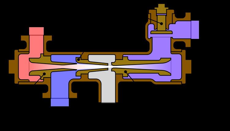
The injector consists of a body containing a series of three or more "cones" containing nozzles along one axis.
It uses the Venturi effect of a converging-diverging nozzle on a steam jet to convert the pressure energy of the steam to velocity energy, reducing its pressure to below atmospheric which enables it to entrain a fluid (eg. water). After passing through the convergent "combining cone", the mixed fluid is fully condensed releasing the latent heat of evaporation of the steam which imparts extra velocity to the water. The condensate mixture then enters a divergent "delivery cone" which slows the jet, converting kinetic energy back into static pressure energy above the pressure of the boiler enabling its feed through a non-return valve.
Most of the heat energy in the condensed steam is returned to the boiler, increasing the thermal efficiency of the process. Injectors are therefore typically over 98% energy-efficient overall; they are also simple compared to the many moving parts in a feed pump.
The motive fluid may be a liquid, steam or any other gas. The entrained suction fluid may be a gas, a liquid, a slurry, or a dust-laden gas stream.
Key design parameters
Fluid feed rate and operating pressure range are the key parameters of an injector, and vacuum pressure and evacuation rate for an ejector.
Compression ratio and the entrainment ratio may also be defined:
The compression ratio of the injector,
The entrainment ratio of the injector,
Lifting Properties
Other key properties of an injector include the fluid inlet pressure requirements i.e. whether it is lifting or non-lifting.
In a non-lifting injector, positive inlet fluid pressure is needed e.g. the cold water-input is fed by gravity.
The steam-cone minimal orifice diameter is kept larger than the combining cone minimal diameter. The non-lifting Nathan 4000 injector used on the Southern Pacific 4294 could push 12,000 US gallons (45,000 L) per hour at 250 psi (17 bar).
The lifting injector can operate with negative inlet fluid pressure i.e. fluid lying below the level of the injector. It differs from the non-lifting type mainly in the relative dimensions of the nozzles.
Overflow
An overflow is required for excess steam or water to discharge, especially during starting; if the injector cannot initially overcome boiler pressure, the overflow allows the injector to continue to draw water and steam.
Check valve
There is at least one check valve (called a "clack valve" in locomotives because of the distinctive noise it makes ) between the exit of the injector and the boiler to prevent back flow, and usually a valve to prevent air being sucked in at the overflow.
Exhaust steam injector
Efficiency was further improved by the development of a multi-stage injector which is powered not by live steam from the boiler but by exhaust steam from the cylinders, thereby making use of the residual energy in the exhaust steam which would otherwise have gone to waste. However, an exhaust injector also cannot work when the locomotive is stationary; later exhaust injectors could use a supply of live steam if no exhaust steam was available.
Problems
Injectors can be troublesome under certain running conditions, when vibration caused the combined steam and water jet to "knock off". Originally the injector had to be restarted by careful manipulation of the steam and water controls, and the distraction caused by a malfunctioning injector was largely responsible for the 1913 Ais Gill rail accident. Later injectors were designed to automatically restart on sensing the collapse in vacuum from the steam jet, for example with a spring-loaded delivery cone.
Another common problem occurs when the incoming water is too warm and is less effective at condensing the steam in the combining cone. This can also occur if the metal body of the injector is too hot, e.g. from prolonged use.
Vacuum ejectors
An additional use for the injector technology is in vacuum ejectors in continuous train braking systems, which were made compulsory in the UK by the Regulation of Railways Act 1889. A vacuum ejector uses steam pressure to draw air out of the vacuum pipe and reservoirs of continuous train brake. Steam locomotives, with a ready source of steam, found ejector technology ideal with its rugged simplicity and lack of moving parts. A steam locomotive usually has two ejectors: a large ejector for releasing the brakes when stationary and a small ejector for maintaining the vacuum against leaks. The small ejector is sometimes replaced by a reciprocating pump driven from the crosshead because this is more economical of steam.
Vacuum brakes have been superseded by air brakes in modern trains, which use pumps, as diesel and electric locomotives no longer have a suitable working fluid for vacuum ejectors.
Earlier application of the principle
An empirical application of the principle was in widespread use on steam locomotives before its formal development as the injector, in the form of the arrangement of the blastpipe and chimney in the locomotive smokebox. The sketch on the right shows a cross section through a smokebox, rotated 90 degrees; it can be seen that the same components are present, albeit differently named, as in the generic diagram of an injector at the top of the article. Exhaust steam from the cylinders is directed through a nozzle on the end of the blastpipe, to reduce pressure inside the smokebox by entraining the flue gases from the boiler which are then ejected via the chimney. The effect is to increase the draught on the fire to a degree proportional to the rate of steam consumption, so that as more steam is used, more heat is generated from the fire and steam production is also increased. The effect was first noted by Richard Trevithick and subsequently developed empirically by the early locomotive engineers; Stephenson's Rocket made use of it, and this constitutes much of the reason for its notably improved performance in comparison with contemporary machines.
Modern uses
The use of injectors (or ejectors) in various industrial applications has become quite common due to their relative simplicity and adaptability. For example:
Well pumps
Jet pumps are commonly used to extract water from water wells. The main pump, often a centrifugal pump, is powered and installed at ground level. Its discharge is split, with the greater part of the flow leaving the system, while a portion of the flow is returned to the jet pump installed below ground in the well. This recirculated part of the pumped fluid is used to power the jet. At the jet pump, the high-energy, low-mass returned flow drives more fluid from the well, becoming a low-energy, high-mass flow which is then piped to the inlet of the main pump.
Shallow well pumps are those in which the jet assembly is attached directly to the main pump and are limited to a depth of approximately 5-8m to prevent cavitation.
Deep well pumps are those in which the jet is located at the bottom of the well. The maximum depth for deep well pumps is determined by the inside diameter of and the velocity through the jet. The major advantage of jet pumps for deep well installations is the ability to situate all mechanical parts (e.g., electric/petrol motor, rotating impellers) at the ground surface for easy maintenance. The advent of the electrical submersible pump has partly replaced the need for jet type well pumps, except for driven point wells or surface water intakes.
Multi-stage steam vacuum ejectors
In practice, for suction pressure below 100 mbar absolute, more than one ejector is used, usually with condensers between the ejector stages. Condensing of motive steam greatly improves ejector set efficiency; both barometric and shell-and-tube surface condensers are used.
In operation a two-stage system consists of a primary high-vacuum (HV) ejector and a secondary low-vacuum (LV) ejector. Initially the LV ejector is operated to pull vacuum down from the starting pressure to an intermediate pressure. Once this pressure is reached, the HV ejector is then operated in conjunction with the LV ejector to finally pull vacuum to the required pressure.
In operation a three-stage system consists of a primary booster, a secondary high-vacuum (HV) ejector, and a tertiary low-vacuum (LV) ejector. As per the two-stage system, initially the LV ejector is operated to pull vacuum down from the starting pressure to an intermediate pressure. Once this pressure is reached, the HV ejector is then operated in conjunction with the LV ejector to pull vacuum to the lower intermediate pressure. Finally the booster is operated (in conjunction with the HV & LV ejectors) to pull vacuum to the required pressure.
Construction materials
Injectors or ejectors are made of carbon steel, stainless steel, titanium, PTFE, carbon, and other materials.