
 | ||
A flow battery, or redox flow battery (after reduction–oxidation), is a type of rechargeable battery where rechargeability is provided by two chemical components dissolved in liquids contained within the system and separated by a membrane. Ion exchange (providing flow of electric current) occurs through the membrane while both liquids circulate in their own respective space. Cell voltage is chemically determined by the Nernst equation and ranges, in practical applications, from 1.0 to 2.2 volts. The performance of these devices is governed by the considerations of electrochemical engineering.
Contents
- Construction principle
- Types
- Redox
- Hybrid
- Membraneless
- Organic
- Metal hydride
- Nano network
- Semi solid
- Chemistries
- Advantages and disadvantages
- Applications
- References
A flow battery is technically akin both to a fuel cell and an electrochemical accumulator cell (electrochemical reversibility). While it has technical advantages such as potentially separable liquid tanks and near unlimited longevity over most conventional rechargeables, current implementations are comparatively less powerful and require more sophisticated electronics.
The energy capacity is a function of the electrolyte volume (amount of liquid electrolyte) and the power a function of the surface area of the electrodes.
Construction principle
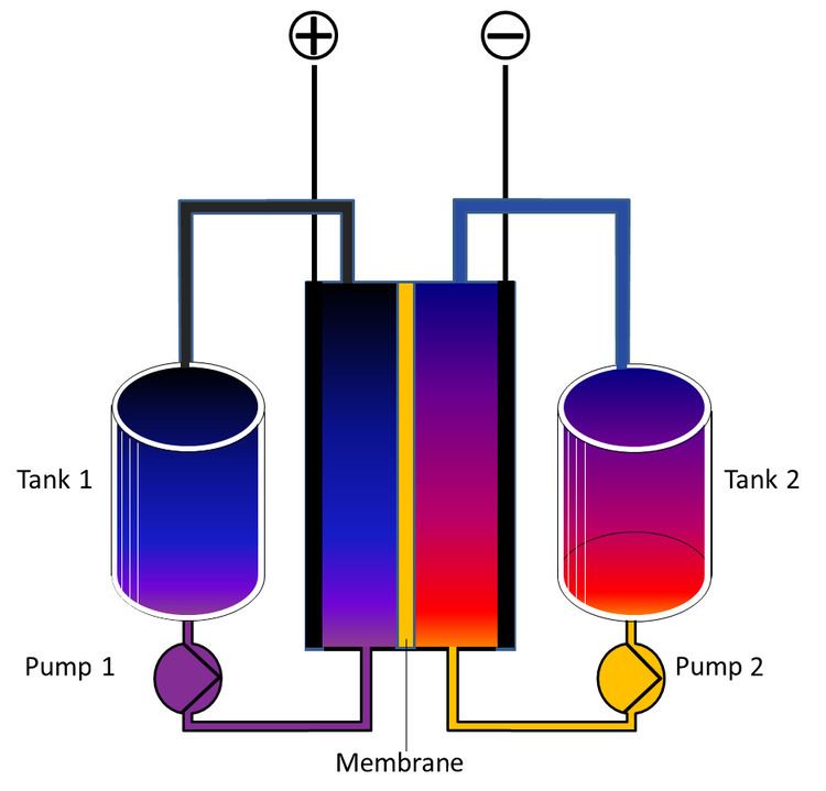
A flow battery is a rechargeable fuel cell in which an electrolyte containing one or more dissolved electroactive elements flows through an electrochemical cell that reversibly converts chemical energy directly to electricity (electroactive elements are "elements in solution that can take part in an electrode reaction or that can be adsorbed on the electrode"). Additional electrolyte is stored externally, generally in tanks, and is usually pumped through the cell (or cells) of the reactor, although gravity feed systems are also known. Flow batteries can be rapidly "recharged" by replacing the electrolyte liquid (in a similar way to refilling fuel tanks for internal combustion engines) while simultaneously recovering the spent material for re-energization.
In other words, a flow battery is just like an electrochemical cell, with the exception that the ionic solution (electrolyte) is not stored in the cell around the electrodes. Rather, the ionic solution is stored outside of the cell, and can be fed into the cell in order to generate electricity. The total amount of electricity that can be generated depends on the size of the storage tanks.
Flow batteries are governed by the design principles established by electrochemical engineering.
Types
Different classes of flow cells (batteries) have been developed, including redox, hybrid and membraneless. The fundamental difference between conventional batteries and flow cells is that energy is stored not as the electrode material in conventional batteries but as the electrolyte in flow cells.
Redox
The redox (reduction–oxidation) cell is a reversible cell in which electrochemical components are dissolved in the electrolyte. Redox flow batteries are rechargeable (secondary cells). Because they employ heterogeneous electron transfer rather than solid-state diffusion or intercalation they are more appropriately called fuel cells than batteries. In industrial practice, fuel cells are usually, and unnecessarily, considered to be primary cells, such as the H
2/O
2 system. The unitized regenerative fuel cell on NASA's Helios Prototype is another reversible fuel cell. The European Patent Organisation classifies redox flow cells (H01M8/18C4) as a sub-class of regenerative fuel cells (H01M8/18). Examples of redox flow batteries are the Vanadium redox flow battery, polysulfide bromide battery (Regenesys), and uranium redox flow battery. Redox fuel cells are less common commercially although many systems have been proposed.
Researchers announced a prototype, zinc-polyiodide flow battery with an energy density of 167 Wh/l (watt-hours per liter). Older zinc-bromide cells reach 70 Wh/l. For comparison, lithium iron phosphate batteries store 233 Wh/l. The zinc-polyiodide battery is claimed to be safer than other flow batteries given its absence of acidic electrolytes, nonflammability and operating range of −4 to 122 °F (−20 to 50 °C) that does not require extensive cooling circuitry, which would add weight and occupy space. One unresolved issue is zinc build-up on the negative electrode that permeated the membrane, reducing efficiency. Because of the Zn dendrite formation, the Zn-halide batteries cannot operate at high current density (> 20 mA/cm2) and thus have limited power density. Adding alcohol to the electrolyte of the ZnI battery can slightly control the problem.
When the battery is fully discharged, both tanks hold the same electrolyte solution: a mixture of positively charged zinc ions (Zn2+
) and negatively charged iodide ion, I-. When charged, one tank holds another negative ion, polyiodide, I3-. The battery produces power by pumping liquid from external tanks into the battery's stack area where the liquids are mixed. Inside the stack, zinc ions pass through a selective membrane and change into metallic zinc on the stack's negative side.
Traditional flow battery chemistries have both low specific energy (which makes them too heavy for fully electric vehicles) and low specific power (which makes them too expensive for stationary energy storage). However, recently a high areal power of 1.4 W/cm2 was demonstrated for hydrogen-bromine flow batteries, and a specific energy (530 Wh/kg at the tank level) was shown for hydrogen-bromate flow batteries
In 2015 a system was demonstrated using organic polymers and a saline solution with a cellulose membrane. The prototype withstood 10000 charging cycles while retaining substantial capacity. The energy density was 10 Wh/l. Current density reached 100 milliamperes/cm2.
Hybrid
The hybrid flow battery uses one or more electroactive components deposited as a solid layer. In this case, the electrochemical cell contains one battery electrode and one fuel cell electrode. This type is limited in energy by the surface area of the electrode.
Hybrid flow batteries include the zinc-bromine, zinc–cerium and lead–acid flow batteries.
Membraneless
This battery employs a phenomenon called laminar flow in which two liquids are pumped through a channel. They undergo electrochemical reactions to store or release energy. The solutions stream through in parallel, with little mixing. The flow naturally separates the liquids, eliminating the need for a membrane.
Membranes are often the most costly component and the most unreliable components of batteries, as they can corrode with repeated exposure to certain reactants. The absence of a membrane enabled the use of a liquid bromine solution and hydrogen. This combination is problematic when membranes are used, because they form hydrobromic acid that can destroy the membrane. Both materials are available at low cost.
The design uses a small channel between two electrodes. Liquid bromine flows through the channel over a graphite cathode and hydrobromic acid flows under a porous anode. At the same time, hydrogen gas flows across the anode. The chemical reaction can be reversed to recharge the battery—a first for any membraneless design. One such membraneless flow battery published in August 2013 produced a maximum power density of 7950 W/m2, three times as much power as other membraneless systems— and an order of magnitude higher than lithium-ion batteries.
Primus Power has developed patented technology in its zinc bromine flow battery, a type of redox flow battery, to eliminate the membrane or separator, which reduces costs and reduces failure rates. The Primus Power membraneless redox flow battery is working in installations in the United States and Asia with a second generation product announced February 21, 2017. Primus Power EnergyPod 2 is in production.
Organic
Compared to traditional aqueous inorganic redox flow batteries such as vanadium redox flow batteries and Zn-Br2 batteries, that have been developed for decades, organic redox flow batteries have emerged since 2009 and hold great promise to overcome major drawbacks preventing economical and extensive deployment of traditional inorganic redox flow batteries. The primary merit of organic redox flow batteries lies in using sustainable and tunable organic redox active molecules, free of resource limitations and enabling unlimited combinations of anode and cathode materials.
Organic redox flow batteries should be classified into two categories: Aqueous Organic Redox Flow Batteries (AORFBs) and Non-aqueous Organic Redox Flow Batteries (NAORFBs). AORFBs use water as solvent for electrolyte materials while NAORFBs employ organic solvents to dissolve redox active materials. Depending on using one or two organic redox active electrolytes as anode and/or cathode, AORFBs and NAORFBs can be further divided into total organic systems and hybrid organic systems that use inorganic materials for anode or cathode. The proof of concept of AORFBs was demonstrated before NAORFBs. In larger-scale energy storage, AORFBs hold much greater potential than NAORFBs because of the former's lower cost, higher current and power performance, as well as safety advantages of aqueous over non-aqueous electrolytes. NAORFBs may find their place in limited special applications for their higher energy density than AORFBs though more challenges are to be overcome in terms of safety, cost of organic solvents, radical induced side reactions, electrolyte crossover and limited life time. The content below mainly covers the representative studies on AORFBs.
The very first studies using simple quinone compounds for AORFBs were reported by Wen et al from China in 2009 and 2010. In their studies, 1,2-dihydrobenzoquinone-3,5-disulfonic acid (BQDS) or 1,4-dihydrobenzoquinone-2-sulfonic acid (BQS) were employed as cathode and conventional Pb/PbSO4 as anolyte in an acid AORFB. These first AORFBs are hybrid systems as they only use organic redox active materials for cathode side while using Pb/PbSO4 for anode side. Each of the carbon-based molecules holds two units of electrical charge, compared with one unit in conventional batteries, implying that a battery could store twice as much energy in a given volume. Quinone compounds have been widely used in many research fields and their synthesis has been well established. However, to develop highly water soluble quinone compounds with optimized reduction or oxidation potential is not straightforward. PbSO4 is a toxic electrolyte used in traditional lead-acid batteries.
In 2014, researchers including Aziz from Harvard University announced the use of 9,10-anthraquinone-2,7-disulphonic acid (AQDS), a quinone, as a charge carrier in metal-free flow batteries. AQDS undergoes rapid, reversible two-electron/two-proton reduction on a glassy carbon electrode in sulphuric acid. An aqueous flow battery with inexpensive carbon electrodes, combining the quinone/hydroquinone couple with the Br
2/Br−
redox couple, yields a peak galvanic power density exceeding 6,000 W/m2 at 13,000 A/m2. Cycling showed >99 per cent storage capacity retention per cycle. Volumetric energy density was over 20 Wh/l. The organic anthraquinone species can be synthesized from inexpensive commodity chemicals. This organic approach permits tuning of the reduction potential and solubility by adding functional groups. Adding two hydroxy groups to AQDS increases the open circuit potential of the cell by 11%. The major concern of this work is the use of toxic Br2 electrolyte and its crossover behavior can lower the battery's energy efficiency.
In 2014, another example was reported by Narayanan and Yang et al from University of Southern Califonia using anthraquinone-2-sulfonic acid or anthraquinone-2,6-disulfonic acid on the negative side and 1,2-dihydrobenzoquinone- 3,5-disulfonic acid on the positive side avoiding the use of hazardous inorganic materials such as Br2. The battery was claimed to last for 1,000 cycles without degradation although no official data were published. While this total organic system appears robust, it has a low cell voltage (ca. 0.55 V) and a low energy density (< 4 Wh/L).
In 2015, Harvard researchers improved the chemistry and replaced the hydrobromic acid used as an electrolyte with a far less toxic alkaline solution (1M KOH) and ferrocyanide. The higher pH is less corrosive, allowing the use of inexpensive polymer tanks. The increased electrical resistance in the membrane was compensated by increasing the voltage. The cell voltage was 1.2. The cell's efficiency exceeded 99%, while round-trip efficiency measured 84%. The battery has an expected lifetime of at least 1,000 cycles. Its theoretic energy density was 19 Wh per liter. Ferrocyanide's chemically stability in high pH KOH solution without forming Fe(OH)2 or Fe(OH)3 needs to be verified before scale-up.
In 2015, Liu and Wang et al from Utah State University and Pacific Northwest National Laboratory announced another project of a totally organic AORFB employing methyl viologen as anolyte and 4-hydroxy-2,2,6,6-tetramethylpiperidin-1-oxyl as catholyte, plus cheap, non-crossive sodium chloride and a low-cost anion exchange membrane to enable charging and discharging. This MV/TEMPO AORFB has the highest cell voltage, 1.25 V, and, possibly, lowest capital cost ($180/kWh) reported for AORFBs. The water-based liquid electrolytes were designed as a drop-in replacement for current systems without replacing existing infrastructure. A 600-milliwatt test battery was stable for 100 cycles with nearly 100 percent efficiency at current densities ranging from 20 to 100 mA per square centimeter, with optimal performance rated at 40-50 mA, at which about 70 percent of the battery's original voltage was retained. The significance of the research is that neutral AORFBs can be more environmentally friendly than acid or alkaline AORFBs while showing electrochemical performance comparable to corrosive acidic or alkaline RFBs. The MV/TEMPO AORFB has an energy density of 8.4 Wh/L with the limitation on the TEMPO side. The next step is to identify a high capacity catholyte to match MV (ca. 3.5 M solubility in water, 93.8 Ah/L).
A new flow-battery concept that is based on redox active, organic polymers based on viologen and TEMPO and dialysis membranes was announced in 2015 (group of Prof. Dr. Ulrich S. Schubert). The polymer-based redox-flow battery (pRFB) uses functionalized macromolecules (similar to acrylic glass or Styrofoam) being dissolved in water as active material for the anode as well as the cathode. Thereby, metals and strongly corrosive electrolytes – like vanadium salts in sulfuric acid – are avoided and simple dialysis membranes can be employed. The membrane, which separates the cathode and the anode of the flow cell, works like a strainer and is produced much more easily and at lower cost than conventional ion-selective membranes. It retains the big “spaghetti”-like polymer molecules, while allowing the small counterions to pass. The concept may solve the high cost of traditional Nafion membrane but the design and synthesis of redox active polymer with high solubility in water is not trivial.
Metal hydride
Proton flow batteries integrate a metal hydride storage electrode into a reversible proton exchange membrane (PEM) fuel cell. During charging, PFB combines hydrogen ions produced from splitting water with electrons and metal particles in one electrode of a fuel cell. The energy is stored in the form of a solid-state metal hydride. Discharge produces electricity and water when the process is reversed and the protons are combined with ambient oxygen. Metals less expensive than lithium can be used and provide greater energy density than lithium cells.
Nano-network
In 2014 a technology was announced that uses lithium–sulfur chemistry arranged in a network of nanoparticles. The network eliminates the requirement that charge moves in and out of particles that are in direct contact with a conducting plate. Instead, the nanoparticle network allows electricity to flow throughout the liquid. This allows more energy to be extracted.
Semi-solid
In a semi-solid flow cell, the positive and negative electrodes are composed of particles suspended in a carrier liquid. The positive and negative suspensions are stored in separate tanks and pumped through separate pipes into a stack of adjacent reaction chambers, where they are separated by a barrier such as a thin, porous membrane. The approach combines the basic structure of aqueous-flow batteries, which use electrode material dissolved in a liquid electrolyte, with the chemistry of lithium-ion batteries. Dissolving a material changes its chemical behavior significantly. However, suspending bits of solid material preserves the solid's characteristics. The result is a viscous suspension that flows like molasses.
Chemistries
There is a wide range of chemistries that have been tried for flow batteries.
Advantages and disadvantages
Redox flow batteries, and to a lesser extent hybrid flow batteries, have the advantages of flexible layout (due to separation of the power and energy components), long cycle life (because there are no solid-to-solid phase transitions), quick response times, no need for "equalisation" charging (the overcharging of a battery to ensure all cells have an equal charge) and no harmful emissions. Some types also offer easy state-of-charge determination (through voltage dependence on charge), low maintenance and tolerance to overcharge/overdischarge. Compared to solid-state rechargeable batteries such as Li ion, RFBs, and ARFBs in particular, can operate at much higher current and power densities. These technical merits make redox flow batteries a well-suited option for large-scale energy storage.
On the negative side, the energy densities vary considerably but are, in general, lower compared to portable batteries, such as the Li-ion.
Applications
Flow batteries are normally considered for relatively large (1 kWh – 10 MWh) stationary applications. These are for