
 | ||
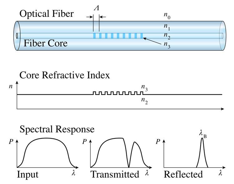
A fiber Bragg grating (FBG) is a type of distributed Bragg reflector constructed in a short segment of optical fiber that reflects particular wavelengths of light and transmits all others. This is achieved by creating a periodic variation in the refractive index of the fiber core, which generates a wavelength-specific dielectric mirror. A fiber Bragg grating can therefore be used as an inline optical filter to block certain wavelengths, or as a wavelength-specific reflector.
Contents
- History
- Manufacture
- Interference
- Sequential writing
- Photomask
- Point by point
- Production
- Theory
- Types of gratings
- Standard or type I gratings
- Type IA gratings
- Type IIA or type In gratings
- Regenerated gratings
- Type II gratings
- Grating structure
- Apodized gratings
- Chirped fiber Bragg gratings
- Tilted fiber Bragg gratings
- Long period gratings
- Communications
- Fiber Bragg grating sensors
- Fiber bragg gratings used in fiber lasers
- Process of matching active and passive fibers
- References
History
The first in-fiber Bragg grating was demonstrated by Ken Hill in 1978. Initially, the gratings were fabricated using a visible laser propagating along the fiber core. In 1989, Gerald Meltz and colleagues demonstrated the much more flexible transverse holographic inscription technique where the laser illumination came from the side of the fiber. This technique uses the interference pattern of ultraviolet laser light to create the periodic structure of the fiber Bragg grating.
Manufacture
Fiber Bragg gratings are created by "inscribing" or "writing" systematic (periodic or aperiodic) variation of refractive index into the core of a special type of optical fiber using an intense ultraviolet (UV) source such as a UV laser. Two main processes are used: interference and masking. The method that is preferable depends on the type of grating to be manufactured. Normally a germanium-doped silica fiber is used in the manufacture of fiber Bragg gratings. The germanium-doped fiber is photosensitive, which means that the refractive index of the core changes with exposure to UV light. The amount of the change depends on the intensity and duration of the exposure as well as the photosensitivity of the fibre. To write a high reflectivity fiber Bragg grating directly in the fiber the level of doping with germanium needs to be high. However, standard fibers can be used if the photosensitivity is enhanced by pre-soaking the fiber in hydrogen. More recently, fiber Bragg gratings have also been written in polymer fibers, this is described in the PHOSFOS entry.
Interference
This was the first method used widely for the fabrication of fiber Bragg gratings and uses two-beam interference. Here the UV laser is split into two beams which interfere with each other creating a periodic intensity distribution along the interference pattern. The refractive index of the photosensitive fiber changes according to the intensity of light that it is exposed to. This method allows for quick and easy changes to the Bragg wavelength, which is directly related to the interference period and a function of the incident angle of the laser light.
Sequential writing
Complex grating profiles can be manufactured by exposing a large number of small, partially overlapping gratings in sequence. Advanced properties such as phase shifts and varying modulation depth can be introduced by adjusting the corresponding properties of the subgratings. In the first version of the method, subgratings were formed by exposure with UV pulses, but this approach had several drawbacks, such as large energy fluctuations in the pulses and low average power. A sequential writing method with continuous UV radiation that overcomes these problems has been demonstrated and is now used commercially. The photosensitive fiber is translated by an interferometrically controlled airbearing borne carriage. The interfering UV beams are focused onto the fiber, and as the fiber moves, the fringes move along the fiber by translating mirrors in an interferometer. As the mirrors have a limited range, they must be reset every period, and the fringes move in a sawtooth pattern. All grating parameters are accessible in the control software, and it is therefore possible to manufacture arbitrary gratings structures without any changes in the hardware.
Photomask
A photomask having the intended grating features may also be used in the manufacture of fiber Bragg gratings. The photomask is placed between the UV light source and the photosensitive fiber. The shadow of the photomask then determines the grating structure based on the transmitted intensity of light striking the fiber. Photomasks are specifically used in the manufacture of chirped Fiber Bragg gratings, which cannot be manufactured using an interference pattern.
Point-by-point
A single UV laser beam may also be used to 'write' the grating into the fiber point-by-point. Here, the laser has a narrow beam that is equal to the grating period. The main difference of this method lies in the interaction mechanisms between infrared laser radiation and dielectric material - multiphoton absorption and tunnel ionization. This method is specifically applicable to the fabrication of long period fiber gratings. Point-by-point is also used in the fabrication of tilted gratings.
Production
Originally, the manufacture of the photosensitive optical fiber and the 'writing' of the fiber Bragg grating were done separately. Today, production lines typically draw the fiber from the preform and 'write' the grating, all in a single stage. As well as reducing associated costs and time, this also enables the mass production of fiber Bragg gratings. Mass production is in particular facilitating applications in smart structures utilizing large numbers (3000) of embedded fiber Bragg gratings along a single length of fiber.
Theory
The fundamental principle behind the operation of an FBG is Fresnel reflection,where light traveling between media of different refractive indices may both reflect and refract at the interface.
The refractive index will typically alternate over a defined length. The reflected wavelength (
where
The wavelength spacing between the first minima (nulls, see Fig. 2), or the bandwidth (
where
The peak reflection (
where
where,
Types of gratings
The term type in this context refers to the underlying photosensitivity mechanism by which grating fringes are produced in the fiber. The different methods of creating these fringes have a significant effect on physical attributes of the produced grating, particularly the temperature response and ability to withstand elevated temperatures. Thus far, five (or six) types of FBG have been reported with different underlying photosensitivity mechanisms. These are summarized below:
Standard, or type I, gratings
Written in both hydrogenated and non-hydrogenated fiber of all types, type I gratings are usually known as standard gratings and are manufactured in fibers of all types under all hydrogenation conditions. Typically, the reflection spectra of a type I grating is equal to 1-T where T is the transmission spectra. This means that the reflection and transmission spectra are complementary and there is negligible loss of light by reflection into the cladding or by absorption. Type I gratings are the most commonly used of all grating types, and the only types of grating available off-the-shelf at the time of writing.
Type IA gratings
Type IA gratings were first observed in 2001 during experiments designed to determine the effects of hydrogen loading on the formation of IIA gratings in germanosilicate fiber. In contrast to the anticipated decrease (or 'blue shift') of the gratings' Bragg wavelength, a large increase (or 'red shift') was observed.
Later work showed that the increase in Bragg wavelength began once an initial type I grating had reached peak reflectivity and begun to weaken. For this reason, it was labeled as a regenerated grating.
Determination of the type IA gratings' temperature coefficient showed that it was lower than a standard grating written under similar conditions.
The key difference between the inscriprion of type IA and IIA gratings is that IA gratings are written in hydrogenated fibres, whereas type IIA gratings are written in non-hydrogenated fibres.
Type IIA, or type In, gratings
Later research by Xie et al. showed the existence of another type of grating with similar thermal stability properties to the type II grating. This grating exhibited a negative change in the mean index of the fiber and was termed type IIA. The gratings were formed in germanosilicate fibers with pulses from a frequency doubled XeCl pumped dye laser. It was shown that initial exposure formed a standard (type I) grating within the fiber which underwent a small red shift before being erased. Further exposure showed that a grating reformed which underwent a steady blue shift whilst growing in strength.
Regenerated gratings
These are gratings that are reborn at higher temperatures after erasure of gratings, usually type I gratings and usually, though not always, in the presence of hydrogen. They have been interpreted in different ways including dopant diffusion (oxygen being the most popular current interpretation) and glass structural change. Recent work has shown that there exists a regeneration regime beyond diffusion where gratings can be made to operate at temperatures in excess of 1,295 °C, outperforming even type II femtosecond gratings. These are extremely attractive for ultra high temperature applications.
Type II gratings
Archambault et al. showed that it was possible to inscribe gratings of ~100% (>99.8%) reflectance with a single UV pulse in fibers on the draw tower. The resulting gratings were shown to be stable at temperatures as high as 800 °C (up to 1,000 °C in some cases, and higher with femtosecond laser inscription). The gratings were inscribed using a single 40 mJ pulse from an excimer laser at 248 nm. It was further shown that a sharp threshold was evident at ~30 mJ; above this level the index modulation increased by more than two orders of magnitude, whereas below 30 mJ the index modulation grew linearly with pulse energy. For ease of identification, and in recognition of the distinct differences in thermal stability, they labeled gratings fabricated below the threshold as type I gratings and above the threshold as type II gratings. Microscopic examination of these gratings showed a periodic damage track at the grating’s site within the fiber [10]; hence type II gratings are also known as damage gratings. However, these cracks can be very localized so as to not play a major role in scattering loss if properly prepared.
Grating structure
The structure of the FBG can vary via the refractive index, or the grating period. The grating period can be uniform or graded, and either localised or distributed in a superstructure. The refractive index has two primary characteristics, the refractive index profile, and the offset. Typically, the refractive index profile can be uniform or apodized, and the refractive index offset is positive or zero.
There are six common structures for FBGs;
- uniform positive-only index change,
- Gaussian apodized,
- raised-cosine apodized,
- chirped,
- discrete phase shift, and
- superstructure.
The first complex grating was made by J. Canning in 1994. This supported the development of the first distributed feedback (DFB) fiber lasers, and also laid the groundwork for most complex gratings that followed, including the sampled gratings first made by Peter Hill and colleagues in Australia.
Apodized gratings
There are basically two quantities that control the properties of the FBG. These are the grating length,
and the grating strength,
Chirped fiber Bragg gratings
The refractive index profile of the grating may be modified to add other features, such as a linear variation in the grating period, called a chirp. The reflected wavelength changes with the grating period, broadening the reflected spectrum. A grating possessing a chirp has the property of adding dispersion—namely, different wavelengths reflected from the grating will be subject to different delays. This property has been used in the development of phased-array antenna systems and polarization mode dispersion compensation, as well.
Tilted fiber Bragg gratings
In standard FBGs, the grading or variation of the refractive index is along the length of the fiber (the optical axis), and is typically uniform across the width of the fiber. In a tilted FBG (TFBG), the variation of the refractive index is at an angle to the optical axis. The angle of tilt in a TFBG has an effect on the reflected wavelength, and bandwidth.
Long-period gratings
Typically the grating period is the same size as the Bragg wavelength, as shown above. For a grating that reflects at 1,500 nm, the grating period is 500 nm, using a refractive index of 1.5. Longer periods can be used to achieve much broader responses than are possible with a standard FBG. These gratings are called long-period fiber grating. They typically have grating periods on the order of 100 micrometers, to a millimeter, and are therefore much easier to manufacture.
Different coatings of diffractive structure are used for fiber Bragg gratings in order to reduce the mechanical impact on the Bragg wavelength shift for 1.1-15 times as compared to an uncoated waveguide.
Communications
The primary application of fiber Bragg gratings is in optical communications systems. They are specifically used as notch filters. They are also used in optical multiplexers and demultiplexers with an optical circulator, or optical add-drop multiplexer (OADM). Figure 5 shows 4 channels, depicted as 4 colours, impinging onto a FBG via an optical circulator. The FBG is set to reflect one of the channels, here channel 4. The signal is reflected back to the circulator where it is directed down and dropped out of the system. Since the channel has been dropped, another signal on that channel can be added at the same point in the network.
A demultiplexer can be achieved by cascading multiple drop sections of the OADM, where each drop element uses an FBG set to the wavelength to be demultiplexed. Conversely, a multiplexer can be achieved by cascading multiple add sections of the OADM. FBG demultiplexers and OADMs can also be tunable. In a tunable demultiplexer or OADM, the Bragg wavelength of the FBG can be tuned by strain applied by a piezoelectric transducer. The sensitivity of a FBG to strain is discussed below in fiber Bragg grating sensors.
Fiber Bragg grating sensors
As well as being sensitive to strain, the Bragg wavelength is also sensitive to temperature. This means that fiber Bragg gratings can be used as sensing elements in optical fiber sensors. In a FBG sensor, the measurand causes a shift in the Bragg wavelength,
or,
Here,
Fiber Bragg gratings can then be used as direct sensing elements for strain and temperature. They can also be used as transduction elements, converting the output of another sensor, which generates a strain or temperature change from the measurand, for example fiber Bragg grating gas sensors use an absorbent coating, which in the presence of a gas expands generating a strain, which is measurable by the grating. Technically, the absorbent material is the sensing element, converting the amount of gas to a strain. The Bragg grating then transduces the strain to the change in wavelength.
Specifically, fiber Bragg gratings are finding uses in instrumentation applications such as seismology, pressure sensors for extremely harsh environments, and as downhole sensors in oil and gas wells for measurement of the effects of external pressure, temperature, seismic vibrations and inline flow measurement. As such they offer a significant advantage over traditional electronic gauges used for these applications in that they are less sensitive to vibration or heat and consequently are far more reliable. In the 1990s, investigations were conducted for measuring strain and temperature in composite materials for aircraft and helicopter structures.
Fiber bragg gratings used in fiber lasers
Recently the development of high power fiber lasers has generated a new set of applications for fiber Bragg gratings (FBG’s), operating at power levels that were previously thought impossible. In the case of a simple fiber laser, the FBG’s can be used as the high reflector (HR) and output coupler (OC) to form the laser cavity. The gain for the laser is provided by a length of rare earth doped optical fiber, with the most common form using Yb3+ ions as the active lasing ion in the silica fiber. These Yb-doped fiber lasers first operated at the 1 kW CW power level in 2004 based on free space cavities but were not shown to operate with fiber Bragg grating cavities until much later.
Such monolithic, all-fiber devices are produced by many companies worldwide and at power levels exceeding 1 kW. The major advantage of these all fiber systems, where the free space mirrors are replaced with a pair of fiber Bragg gratings (FBG’s), is the elimination of realignment during the life of the system, since the FBG is spliced directly to the doped fiber and never needs adjusting. The challenge is to operate these monolithic cavities at the kW CW power level in large mode area (LMA) fibers such as 20/400 (20 um diameter core and 400 um diameter inner cladding) without premature failures at the intra-cavity splice points and the gratings. Once optimized, these monolithic cavities do not need realignment during the life of the device, removing any cleaning and degradation of fiber surface from the maintenance schedule of the laser. However, the packaging and optimization of the splices and FBGs themselves are non-trivial at these power levels as are the matching of the various fibers, since the composition of the Yb-doped fiber and various passive and photosensitive fibers needs to be carefully matched across the entire fiber laser chain. Although the power handling capability of the fiber itself far exceeds this level, and is possibly as high as >30 kW CW, the practical limit is much lower due to component reliability and splice losses.
Process of matching active and passive fibers
In a double-clad fiber there are two waveguides – the Yb-doped core that forms the signal waveguide and the inner cladding waveguide for the pump light. The inner cladding of the active fiber is often shaped to scramble the cladding modes and increase pump overlap with the doped core. The matching of active and passive fibers for improved signal integrity requires optimization of the core/clad concentricity, and the MFD through the core diameter and NA, which reduces splice loss. This is principally achieved by tightening all of the pertinent fiber specifications.
Matching fibers for improved pump coupling requires optimization of the clad diameter for both the passive and the active fiber. To maximize the amount of pump power coupled into the active fiber, the active fiber is designed with a slightly larger clad diameter than the passive fibers delivering the pump power. As an example, passive fibers with clad diameters of 395-um spliced to active octagon shaped fiber with clad diameters of 400-um improve the coupling of the pump power into the active fiber. An image of such a splice is shown, showing the shaped cladding of the doped double-clad fiber.
The matching of active and passive fibers can be optimized in several ways. The easiest method for matching the signal carrying light is to have identical NA and core diameters for each fiber. This however does not account for all the refractive index profile features. Matching of the MFD is also a method used to create matched signal carrying fibers. It has been shown that matching all of these components provides the best set of fibers to build high power amplifiers and lasers. Essentially, the MFD is modeled and the resulting target NA and core diameter are developed. The core-rod is made and before being drawn into fiber its core diameter and NA are checked. Based on the refractive index measurements, the final core/clad ratio is determined and adjusted to the target MFD. This approach accounts for details of the refractive index profile which can be measured easily and with high accuracy on the preform, before it is drawn into fiber.