
 | ||
In mobile-telephone technology, the UniPro protocol stack follows the architecture of the classical OSI Reference Model. In UniPro, the OSI Physical Layer is split into two sublayers: Layer 1 (the actual physical layer) and Layer 1.5 (the PHY Adapter layer) which abstracts from differences between alternative Layer 1 technologies. The actual physical layer is a separate specification as the various PHY options are reused in other MIPI Alliance specifications.
Contents
- D PHY
- M PHY
- Low speed modes and power savings
- PHY Adapter Layer L15
- L15 symbols
- L15 multi lane support
- L15 lane discovery
- L15 link power management
- L15 peer parameters control
- L15 guarantees
- Data Link Layer L2
- L2 data frames
- L2 control frames
- L2 retransmission
- L2 flow control
- L2 Traffic Classes and arbitration
- L2 single Traffic Class option
- L2 guarantees
- Network Layer L3
- L3 addressing
- L3 packets
- L3 short header packet structure
- L3 long header packets
- L3 guarantees
- Transport Layer L4
- L4 features
- L4 segments
- L4 connections
- L4 flow control
- L4 flow control versus L2 flow control
- L4 flow control applicability
- L4 safety net
- L4 and Messages
- L4 guarantees
- Device Management Entity DME
- References
The UniPro specification itself covers Layers 1.5, 2, 3, 4 and the DME (Device Management Entity). The Application Layer (LA) is out of scope because different uses of UniPro will require different LA protocols. The Physical Layer (L1) is covered in separate MIPI specifications in order to allow the PHY to be reused by other (less generic) protocols if needed.
OSI Layers 5 (Session) and 6 (Presentation) are, where applicable, counted as part of the Application Layer.
D-PHY
Versions 1.0 and 1.1 of UniPro use MIPI's D-PHY technology for the off-chip Physical Layer. This PHY allows inter-chip communication. Data rates of the D-PHY are variable, but are in the range of 500-1000 Mbit/s (lower speeds are supported, but at decreased power efficiency). The D-PHY was named after the Roman number for 500 ("D").
The D-PHY uses differential signaling to convey PHY symbols over micro-stripline wiring. A second differential signal pair is used to transmit the associated clock signal from the source to the destination. The D-PHY technology thus uses a total of 2 clock wires per direction plus 2 signal wires per lane and per direction. For example, a D-PHY might use 2 wires for the clock and 4 wires (2 lanes) for the data in the forward direction, but 2 wires for the clock and 6 wires (3 lanes) for the data in the reverse direction. Data traffic in the forward and reverse directions are totally independent at this level of the protocol stack.
In UniPro, the D-PHY is used in a mode (called "8b9b" encoding) which conveys 8-bit bytes as 9-bit symbols. The UniPro protocol uses this to represent special control symbols (outside the usual 0 to 255 values). The PHY itself uses this to represent certain special symbols that have meaning to the PHY itself (e.g. IDLE symbols). Note that the ratio 8:9 can cause some confusion when specifying the data rate of the D-PHY: a PHY implementation running with a 450 MHz clock frequency is often rated as a 900 Mbit/s PHY, while only 800 Mbit/s is then available for the UniPro stack.
The D-PHY also supports a Low-Power Data Transmission (LPDT) mode and various other low-power modes for use when no data needs to be sent.
M-PHY
Versions 1.4 and beyond of UniPro support both the D-PHY as well as M-PHY technology. The M-PHY technology is still in draft status, but supports high-speed data rates starting at about 1000 Mbit/s (the M-PHY was named after the Roman number for 1000). In addition to higher speeds, the M-PHY will use fewer signal wires because the clock signal is embedded with the data through the use of industry-standard 8b10b encoding. Again, a PHY capable of transmitting user data at 1000 Mbit/s is typically specified as being in 1250 Mbit/s mode due to the 8b10b encoding.
The D- and M-PHY are expected to co-exist for several years because the D-PHY is a less complex technology while the M-PHY provides higher bandwidths with fewer signal wires.
Low speed modes and power savings
It is worth noting that UniPro supports the power efficient low speed communication modes provided by both the D-PHY (10 Mbit/s) and M-PHY (3 Mbit/sec up to 500 Mbit/s). In these modes, power consumption roughly scales with the amount of data that is sent. Furthermore, both PHY technologies provide additional power saving modes because they were optimized for use in battery-powered devices.
PHY Adapter Layer (L1.5)
Architecturally, the PHY Adapter layer serves to hide the differences between the different PHY options (D- and M-PHY). This abstraction thus mainly gives architectural flexibility. Abstracted PHY details include the various power states and employed symbol encoding schemes.
L1.5 symbols
L1.5 thus has its own (conceptual) symbol encoding consisting of 17-bit symbols. These 17-bit symbols never show up on the wires, because they are first converted by L1.5 to a pair of PHY symbols. The extra 17th control bit indicates special control symbols which are used by the protocol (L1.5 and L2) itself. In the figures, the control bits are shown in "L1.5 red" as a reminder that they are defined in- and used by protocol Layer 1.5.
L1.5 multi-lane support
The main feature that L1.5 offers users is to allow the bandwidth of a UniPro link to be increased by using 2, 3 or 4 lanes when a single lane does not provide enough bandwidth. To the user, such a multi-lane link simply looks like a faster physical layer because the symbols are sent across 2, 3 or 4 lanes. Applications that require higher bandwidth in one direction but require less bandwidth in the opposite direction, can have different numbers of lanes per direction.
L1.5 lane discovery
Starting in UniPro v1.4, L1.5 automatically discovers the number of usable M-PHY lanes for each direction of the link. This involves a simple discovery protocol within L1.5 that is executed on initialization. The protocol transmits test data on each available outbound lane, and receives information back from the peer entity about which data on which lane actually made it to the other end of the link. The mechanism also supports transparent remapping of the lanes to give circuit board designers flexibility in how the lanes are physically wired.
L1.5 link power management
Starting in UniPro v1.4, L1.5 has a built in protocol called PACP (PA Control Protocol) that allows L1.5 to communicate with its peer L1.5 entity at the other end of an M-PHY-based link. Its main usage is to provide a simple and reliable way for a controller at one end of the link to change the power modes of both the forward and reverse directions of the link. This means that a controller situated at one end of the link can change the power mode of both link directions in a single atomic operation. The intricate steps required for doing this in a fully reliable way are handled transparently within L1.5.
L1.5 peer parameters control
In addition to the L1.5 link power management the PACP is also used to access control and status parameters of the peer UniPro device.
L1.5 guarantees
The mechanisms in L1.5 guarantee the following to upper layer protocols:
Data Link Layer (L2)
The main task of UniPro's Data Link layer (L2) is to allow reliable communication between two adjacent nodes in the network - despite occasional bit errors at the Physical layer or potential link congestion if the receiver cannot absorb the data fast enough.
L2 data frames
L2 clusters 17-bit UniPro L1.5 symbols into packet-like data frames (the term packet is reserved for L3). These data frames start with a 17-bit start-of-frame control symbol, followed by up to 288 bytes of data (144 data symbols) and followed by an end-of-frame control symbol and a checksum.
Note that two or more of the 288 bytes are used by higher layers of the UniPro protocol. The maximum frame size of 288 payload bytes per frame was chosen to ensure that the entire protocol stack could easily transmit 256 bytes of application data in a single chunk. Payloads consisting of odd numbers of bytes are supported by padding the frame to an even number of bytes and inserting a corresponding flag in the trailer.
L2 control frames
In addition to data frames which contain user data, L2 also transmits and receives control frames. The control frames can be distinguished from data frames by three bits in the first symbol. There are two types of control frames:
Note that these L2 types of control frames are sent autonomously by L2.
L2 retransmission
High speed communication at low power levels can lead to occasional errors in the received data. The Data Link layer contains a protocol to automatically acknowledge correctly received data frames (using AFC control frames) and to actively signal errors that can be detected at L2 (using NAC control frames). The most likely cause of an error at L2 is that a data frame was corrupted at the electrical level (noise, EMI). This results in an incorrect data or control frame checksum at the receiver side and will lead to its automatic retransmission. Note that data frames are acknowledged (AFC) or negatively acknowledged (NAC). Corrupt control frames are detected by timers that monitor expected or required responses.
A bandwidth of 1 Gbit/s and a bit-error rate of 10−12 at a speed of 1 gigabit/s would imply an error every 1000 seconds or once every 1000th transmitted Gbit. Layer 2 thus automatically corrects these errors at the cost of marginal loss of bandwidth and at the cost of buffer space needed in L2 to store copies of transmitted data frames for possible retransmission or "replay".
L2 flow control
Another feature of L2 is the ability for an L2 transmitter to know whether there is buffer space for the data frame at the receiving end. This again relies on L2 control frames (AFC) which allow a receiver to tell the peer's transmitter how much buffer space is available. This allows the receiver to pause the transmitter if needed, thus avoiding receive buffer overflow. Control frames are unaffected by L2 flow control: they can be sent at any time and the L2 receiver is expected to process these at the speed at which they arrive.
L2 Traffic Classes and arbitration
UniPro currently supports two priority levels for data frames called Traffic Class 0 (TC0) and Traffic Class 1 (TC1). TC1 has higher priority than TC0. This means that if an L2 transmitter has a mix of TC0 and TC1 data frames to send, the TC1 data frames will be sent first. Assuming that most data traffic uses TC0 and that the network has congestion, this helps ensure that TC1 data frames arrive at their destination faster than TC0 data frames (analogous to emergency vehicles and normal road traffic). Furthermore, L2 can even interrupt or "preempt" an outgoing TC0 data frame to transmit a TC1 data frame. Additional arbitration rules apply to control frames: in essence these receive higher priority than data frames because they are small and essential for keeping traffic flowing.
In a multi-hop network, the arbitration is done within every L2 transmitter at every hop. The Traffic Class assigned to data does not normally change as data progresses through the network. It is up to the applications to decide how to use the priority system.
L2 single Traffic Class option
In UniPro version 1.1, an option was introduced to allow simple endpoint devices to implement only one of the two Traffic Classes if they choose to. This can be useful when device designers are more concerned with implementation cost than with control over frame arbitration. The connected L2 peer device detects such devices during the link initialization phase and can avoid using the missing Traffic Class.
L2 guarantees
The various L2 mechanisms provide a number of guarantees to higher layer protocols:
Thus individual links autonomously provide reliable data transfer. This is different from, for example, the widely used TCP protocol that detects errors at the endpoints and relies on end-to-end retransmission in case of corrupted or missing data.
Network Layer (L3)
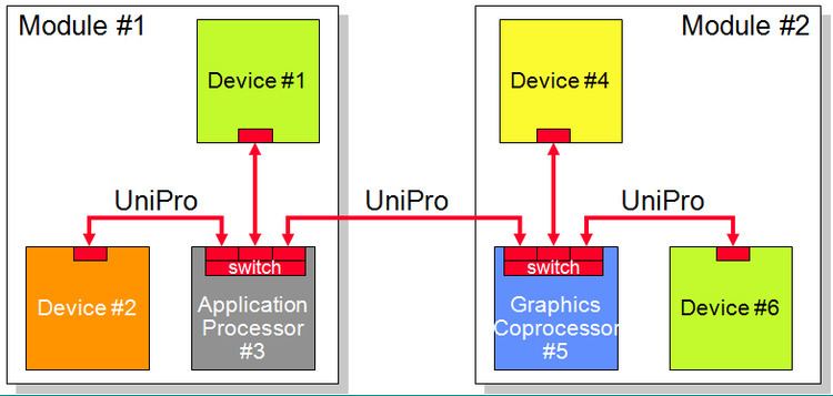
The network layer is intended to route packets through the network toward their destination. Switches within a multi-hop network use this address to decide in which direction to route individual packets. To enable this, a header containing a 7-bit destination address is added by L3 to all L2 data frames. In the example shown in the figure, this allows Device #3 to not only communicate with Device #1, #2 and #5, but also enables it to communicate with Devices #4 and #6.
Version 1.4 of the UniPro spec does not specify the details of a switch, but does specify enough to allow a device to work in a future networked environment.
L3 addressing
Although the role of the L3 address is the same as the IP address in packets on the Internet, a UniPro DeviceID address is only 7 bits long. A network can thus have up to 128 different UniPro devices. Note that, as far as UniPro is concerned, all UniPro devices are created equal: unlike PCI Express or USB, any device can take the initiative to communicate with any other device. This makes UniPro a true network rather than a bus with one master.
L3 packets
The diagram shows an example of an L3 packet which starts at the first L2 payload byte of an L2 frame and ends at the last L2 payload byte of an L2 frame. For simplicity and efficiency, only a single L3 packet can be carried by one L2 frame. This implies that, in UniPro, the concepts of an L2 Frame, an L3 Packet and an L4 Segment (see below) are so closely aligned that they are almost synonyms. The distinction (and "coloring") is however still made to ensure that the specification can be described in a strictly layered fashion.
L3 short-header packet structure
UniPro short-header packets use a single header byte for L3 information. It includes the 7-bit L3 destination address. The remaining bit indicates the short-header packet format. For short-header packets, the L3 source address is not included in the header because it is assumed that the two communicating devices have exchanged such information beforehand (connection-oriented communication).
L3 long-header packets
Long-header packets are intended to be introduced in a future version of the UniPro specification, so their format is undefined (except for one bit) in the current UniPro v1.4 specification. However, UniPro v1.4 defines a hook that allows long-header packets to be received or transmitted by a UniPro v1.4 conformant-device assuming the latter can be upgraded via software. The "long-header trap" mechanism of UniPro v1.4 simply passes the payload of a received L2 data frame (being the L3 packet with its header and payload) to the L3 extension (e.g. software) for processing. The mechanism can also accept L2 frame payload from the L3 extension for transmission. This mechanism aims to allow UniPro v1.4 devices to be able to be upgraded in order to support protocols that require the as-yet undefined long-header packets.
L3 guarantees
Although details of switches are still out of scope in the UniPro v1.4 spec, L3 allows UniPro v1.0/v1.1/v1.4 devices to serve as endpoints on a network. It therefore guarantees a number of properties to higher layer protocols:
Transport Layer (L4)
The features of UniPro's Transport layer are not especially complex, because basic communication services have already been taken care of by lower protocol layers. L4 is essentially about enabling multiple devices on the network or even multiple clients within these devices to share the network in a controlled manner. L4's features tend to be roughly comparable to features found in computer networking (e.g. TCP and UDP) but that are less commonly encountered in local busses like PCI Express, USB or on-chip busses.
UniPro's L4 also has special significance because it is the top protocol layer in the UniPro specification. Applications are required to use L4's top interface to interact with UniPro and are not expected to bypass L4 to directly access lower layers. Note that the interface at the top of L4 provided for transmitting or receiving data is defined at the behavioral or functional level. This high level of abstraction avoids restricting implementation options. Thus, although the specification contains an annex with a signal-level interface as a non-normative example, a UniPro implementation is not required to have any specific set of hardware signals or software function calls at its topmost interface.
L4 features
UniPro's Transport layer can be seen as providing an extra level of addressing within a UniPro device. This
These points are explained in more detail below.
L4 segments
An L4 segment, is essentially the payload of an L3 packet. The L4 header, in its short form, consists of just a single byte. The main field in the short L4 header is a 5-bit "CPort" identifier which can be seen as a sub-address within a UniPro device and is somewhat analogous to the port numbers used in TCP or UDP. Thus every segment (with a short header) is addressed to a specific CPort of specific UniPro device.
A single bit in the segment header also allows segments to be defined with long segment headers. UniPro v1.4 does not define the structure of such segment formats (except for this single bit). Long header segments may be generated via the long header trap described in the L3 section.
L4 connections
UniPro calls a pair of CPorts that communicate with each other a Connection (hence the C in CPort). Setting up a connection means that one CPort has been initialized to create segments which are addressed to a specific L4 CPort of a specific L3 DeviceID using a particular L2 Traffic Class. Because UniPro connections are bidirectional, the destination CPort is also configured to allow data to be sent back to the source CPort.
In UniPro 1.0/1.1 connection setup is implementation specific.
In UniPro v1.4 connection setup is assumed to be relatively static: the parameters of the paired CPorts are configured by setting the corresponding connection Attributes in the local and peer devices using the DME. This will be supplemented by a dynamic connection management protocol in a future version of UniPro.
L4 flow control
CPorts also contain state variables that can be used to track how much buffer space the peer or connected CPort has. This is used to prevent the situation whereby a CPort sends segments to a CPort which has insufficient buffer space to hold the data, thus leading to stalled data traffic. Unless resolved fast, this traffic jam at the destination quickly grows into a network-wide gridlock. This is highly undesirable as it can greatly affect network performance for all users or, worse, can lead to deadlock situations. The described L4 mechanism is known as end-to-end flow control (E2E FC) because it involves the endpoints of a connection.
L4 flow control versus L2 flow control
L4 flow control is complementary to L2 flow control. Both work by having the transmitter pause until it knows there is sufficient buffer space at the receiver. But L4 flow control works between a pair of CPorts (potentially multiple hops apart) and aims to isolate connections from one another ("virtual wire" analogy). In contrast, L2 flow control is per-hop and avoids basic loss of data due to lack of receiver buffer space.
L4 flow control applicability
E2E FC is only possible for connection-oriented communication, but at present UniPro's L4 does not support alternative options. E2E FC is enabled by default but can, however, be disabled. This is not generally recommended.
L4 safety net
UniPro provides "safety net" mechanisms that mandate that a CPort absorbs all data sent to it without stalling. If a stall is detected anyway, the endpoint discards the incoming data arriving at that CPort in order to maintain data flow on the network. This can be seen as a form of graceful degradation at the system level: if one connection on the network cannot keep up with the speed of the received data, other devices and other connections are unaffected.
L4 and Messages
UniPro L4 allows a connection between a pair of CPorts to convey a stream of so-called messages (each consisting of a series of bytes) rather than a single stream of bytes. Message boundaries are triggered by the application-level protocol using UniPro and are signaled via a bit in the segment header. This End-of-Message bit indicates that the last byte in the L4 segment is the last byte of the application-level message.
UniPro needs to be told by the application where or when to insert message boundaries into the byte stream: the boundaries have no special meaning for UniPro itself and are provided as a service to build higher-layer protocols on top of UniPro. Messages can be used to indicate (e.g. via an interrupt) to the application that a unit of data is complete and can thus be processed. Messages can also be useful as a robust and efficient mechanism to implement resynchronization points in some applications.
UniPro v1.4 introduces the notion of message fragment, a fragment being a portion of a message passed between the application and the CPort. This option can be useful when specifying Applications on top of UniPro that need to interrupt the Message creation based on information from the UniPro stack, e.g., incoming Messages, or backpressure.
L4 guarantees
The mechanisms in L4 provide a number of guarantees to upper layer protocols:
Device Management Entity (DME)
The DME (Device Management Entity) controls the layers in the UniPro stack. It provides access to control and status parameters in all layers, manages the power mode transitions of the Link and handles the boot-up, hibernate and reset of the stack. Furthermore, it provides means to control the peer UniPro stack on the Link.