
 | ||
The Open Systems Interconnection model (OSI model) is a conceptual model that characterizes and standardizes the communication functions of a telecommunication or computing system without regard to their underlying internal structure and technology. Its goal is the interoperability of diverse communication systems with standard protocols. The model partitions a communication system into abstraction layers. The original version of the model defined seven layers.
Contents
- History
- Description of OSI layers
- Layer 1 Physical Layer
- Layer 2 Data Link Layer
- Layer 3 Network Layer
- Layer 4 Transport Layer
- Layer 5 Session Layer
- Layer 6 Presentation Layer
- Layer 7 Application Layer
- Cross layer functions
- Interfaces
- Comparison with TCPIP model
- References
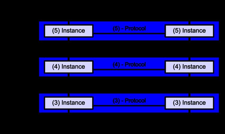
A layer serves the layer above it and is served by the layer below it. For example, a layer that provides error-free communications across a network provides the path needed by applications above it, while it calls the next lower layer to send and receive packets that comprise the contents of that path. Two instances at the same layer are visualized as connected by a horizontal connection in that layer.
The model is a product of the Open Systems Interconnection project at the International Organization for Standardization (ISO), maintained by the identification ISO/IEC 7498-1.
History
In the late 1970s, one project was administered by the International Organization for Standardization (ISO), while another was undertaken by the International Telegraph and Telephone Consultative Committee, or CCITT (the abbreviation is from the French version of the name). These two international standards bodies each developed a document that defined similar networking models.
In 1983, these two documents were merged to form a standard called The Basic Reference Model for Open Systems Interconnection. The standard is usually referred to as the Open Systems Interconnection Reference Model, the OSI Reference Model, or simply the OSI model. It was published in 1984 by both the ISO, as standard ISO 7498, and the renamed CCITT (now called the Telecommunications Standardization Sector of the International Telecommunication Union or ITU-T) as standard X.200.
OSI had two major components, an abstract model of networking, called the Basic Reference Model or seven-layer model, and a set of specific protocols.
The concept of a seven-layer model was provided by the work of Charles Bachman at Honeywell Information Services. Various aspects of OSI design evolved from experiences with the ARPANET, NPLNET, EIN, CYCLADES network and the work in IFIP WG6.1. The new design was documented in ISO 7498 and its various addenda. In this model, a networking system was divided into layers. Within each layer, one or more entities implement its functionality. Each entity interacted directly only with the layer immediately beneath it, and provided facilities for use by the layer above it.
Protocols enable an entity in one host to interact with a corresponding entity at the same layer in another host. Service definitions abstractly described the functionality provided to an (N)-layer by an (N-1) layer, where N was one of the seven layers of protocols operating in the local host.
The OSI standards documents are available from the ITU-T as the X.200-series of recommendations. Some of the protocol specifications were also available as part of the ITU-T X series. The equivalent ISO and ISO/IEC standards for the OSI model were available from ISO, not all are free of charge.
Description of OSI layers
The recommendation X.200 describes seven layers, labeled 1 to 7. Layer 1 is the lowest layer in this model.
At each level N, two entities at the communicating devices (layer N peers) exchange protocol data units (PDUs) by means of a layer N protocol. Each PDU contains a payload, called the service data unit (SDU), along with protocol-related headers or footers.
Data processing by two communicating OSI-compatible devices is done as such:
- The data to be transmitted is composed at the topmost layer of the transmitting device (layer N) into a protocol data unit (PDU).
- The PDU is passed to layer N-1, where it is known as the service data unit (SDU).
- At layer N-1 the SDU is concatenated with a header, a footer, or both, producing a layer N-1 PDU. It is then passed to layer N-2.
- The process continues until reaching the lowermost level, from which the data is transmitted to the receiving device.
- At the receiving device the data is passed from the lowest to the highest layer as a series of SDUs while being successively stripped from each layer's header or footer, until reaching the topmost layer, where the last of the data is consumed.
Some orthogonal aspects, such as management and security, involve all of the layers (See ITU-T X.800 Recommendation). These services are aimed at improving the CIA triad - confidentiality, integrity, and availability - of the transmitted data. In practice, the availability of a communication service is determined by the interaction between network design and network management protocols. Appropriate choices for both of these are needed to protect against denial of service.
Layer 1: Physical Layer
The physical layer defines the electrical and physical specifications of the data connection. It defines the relationship between a device and a physical transmission medium (e.g., a copper or fiber optical cable, radio frequency). This includes the layout of pins, voltages, line impedance, cable specifications, signal timing and similar characteristics for connected devices and frequency (5 GHz or 2.4 GHz etc.) for wireless devices. It is responsible for transmission and reception of unstructured raw data in a physical medium. It may define transmission mode as simplex, half duplex, and full duplex. It defines the network topology as bus, mesh, or ring being some of the most common.
The physical layer of Parallel SCSI operates in this layer, as do the physical layers of Ethernet and other local-area networks, such as token ring, FDDI, ITU-T G.hn, and IEEE 802.11 (Wi-Fi), as well as personal area networks such as Bluetooth and IEEE 802.15.4.
The physical layer is the layer of low-level networking equipment, such as some hubs, cabling, and repeaters. The physical layer is never concerned with protocols or other such higher-layer items. Examples of hardware in this layer are network adapters, repeaters, network hubs, modems, and fiber media converters.
Layer 2: Data Link Layer
The data link layer provides node-to-node data transfer—a link between two directly connected nodes. It detects and possibly corrects errors that may occur in the physical layer. It defines the protocol to establish and terminate a connection between two physically connected devices. It also defines the protocol for flow control between them.
IEEE 802 divides the data link layer into two sublayers:
The MAC and LLC layers of IEEE 802 networks such as 802.3 Ethernet, 802.11 Wi-Fi, and 802.15.4 ZigBee operate at the data link layer.
The Point-to-Point Protocol (PPP) is a data link layer protocol that can operate over several different physical layers, such as synchronous and asynchronous serial lines.
The ITU-T G.hn standard, which provides high-speed local area networking over existing wires (power lines, phone lines and coaxial cables), includes a complete data link layer that provides both error correction and flow control by means of a selective-repeat sliding-window protocol.
Layer 3: Network Layer
The network layer provides the functional and procedural means of transferring variable length data sequences (called datagrams) from one node to another connected to the same "network". A network is a medium to which many nodes can be connected, on which every node has an address and which permits nodes connected to it to transfer messages to other nodes connected to it by merely providing the content of a message and the address of the destination node and letting the network find the way to deliver the message to the destination node, possibly routing it through intermediate nodes. If the message is too large to be transmitted from one node to another on the data link layer between those nodes, the network may implement message delivery by splitting the message into several fragments at one node, sending the fragments independently, and reassembling the fragments at another node. It may, but need not, report delivery errors.
Message delivery at the network layer is not necessarily guaranteed to be reliable; a network layer protocol may provide reliable message delivery, but it need not do so.
A number of layer-management protocols, a function defined in the management annex, ISO 7498/4, belong to the network layer. These include routing protocols, multicast group management, network-layer information and error, and network-layer address assignment. It is the function of the payload that makes these belong to the network layer, not the protocol that carries them.
Layer 4: Transport Layer
The transport layer provides the functional and procedural means of transferring variable-length data sequences from a source to a destination host via one or more networks, while maintaining the quality of service functions.
An example of a transport-layer protocol in the standard Internet stack is Transmission Control Protocol (TCP), usually built on top of the Internet Protocol (IP).
The transport layer controls the reliability of a given link through flow control, segmentation/desegmentation, and error control. Some protocols are state- and connection-oriented. This means that the transport layer can keep track of the segments and re-transmit those that fail. The transport layer also provides the acknowledgement of the successful data transmission and sends the next data if no errors occurred. The transport layer creates packets out of the message received from the application layer. Packetizing is a process of dividing the long message into smaller messages.
OSI defines five classes of connection-mode transport protocols ranging from class 0 (which is also known as TP0 and provides the fewest features) to class 4 (TP4, designed for less reliable networks, similar to the Internet). Class 0 contains no error recovery, and was designed for use on network layers that provide error-free connections. Class 4 is closest to TCP, although TCP contains functions, such as the graceful close, which OSI assigns to the session layer. Also, all OSI TP connection-mode protocol classes provide expedited data and preservation of record boundaries. Detailed characteristics of TP0-4 classes are shown in the following table:
An easy way to visualize the transport layer is to compare it with a post office, which deals with the dispatch and classification of mail and parcels sent. Do remember, however, that a post office manages the outer envelope of mail. Higher layers may have the equivalent of double envelopes, such as cryptographic presentation services that can be read by the addressee only. Roughly speaking, tunneling protocols operate at the transport layer, such as carrying non-IP protocols such as IBM's SNA or Novell's IPX over an IP network, or end-to-end encryption with IPsec. While Generic Routing Encapsulation (GRE) might seem to be a network-layer protocol, if the encapsulation of the payload takes place only at endpoint, GRE becomes closer to a transport protocol that uses IP headers but contains complete frames or packets to deliver to an endpoint. L2TP carries PPP frames inside transport packet.
Although not developed under the OSI Reference Model and not strictly conforming to the OSI definition of the transport layer, the Transmission Control Protocol (TCP) and the User Datagram Protocol (UDP) of the Internet Protocol Suite are commonly categorized as layer-4 protocols within OSI.
Layer 5: Session Layer
The session layer controls the dialogues (connections) between computers. It establishes, manages and terminates the connections between the local and remote application. It provides for full-duplex, half-duplex, or simplex operation, and establishes checkpointing, adjournment, termination, and restart procedures. The OSI model made this layer responsible for graceful close of sessions, which is a property of the Transmission Control Protocol, and also for session checkpointing and recovery, which is not usually used in the Internet Protocol Suite. The session layer is commonly implemented explicitly in application environments that use remote procedure calls.
Layer 6: Presentation Layer
The presentation layer establishes context between application-layer entities, in which the application-layer entities may use different syntax and semantics if the presentation service provides a mapping between them. If a mapping is available, presentation service data units are encapsulated into session protocol data units, and passed down the protocol stack.
This layer provides independence from data representation (e.g., encryption) by translating between application and network formats. The presentation layer transforms data into the form that the application accepts. This layer formats and encrypts data to be sent across a network. It is sometimes called the syntax layer.
The original presentation structure used the Basic Encoding Rules of Abstract Syntax Notation One (ASN.1), with capabilities such as converting an EBCDIC-coded text file to an ASCII-coded file, or serialization of objects and other data structures from and to XML.
Layer 7: Application Layer
The application layer is the OSI layer closest to the end user, which means both the OSI application layer and the user interact directly with the software application. This layer interacts with software applications that implement a communicating component. Such application programs fall outside the scope of the OSI model. Application-layer functions typically include identifying communication partners, determining resource availability, and synchronizing communication. When identifying communication partners, the application layer determines the identity and availability of communication partners for an application with data to transmit. When determining resource availability, the application layer must decide whether sufficient network resources for the requested communication are available.
Cross-layer functions
Cross-layer functions are services that are not tied to a given layer, but may affect more than one layer. Examples include the following:
Interfaces
Neither the OSI Reference Model nor OSI protocols specify any programming interfaces, other than deliberately abstract service specifications. Protocol specifications precisely define the interfaces between different computers, but the software interfaces inside computers, known as network sockets are implementation-specific.
For example, Microsoft Windows' Winsock, and Unix's Berkeley sockets and System V Transport Layer Interface, are interfaces between applications (layer 5 and above) and the transport (layer 4). NDIS and ODI are interfaces between the media (layer 2) and the network protocol (layer 3).
Interface standards, except for the physical layer to media, are approximate implementations of OSI service specifications.
Comparison with TCP/IP model
The design of protocols in the TCP/IP model of the Internet does not concern itself with strict hierarchical encapsulation and layering. RFC 3439 contains a section entitled "Layering considered harmful". TCP/IP does recognize four broad layers of functionality which are derived from the operating scope of their contained protocols: the scope of the software application; the end-to-end transport connection; the internetworking range; and the scope of the direct links to other nodes on the local network.
Despite using a different concept for layering than the OSI model, these layers are often compared with the OSI layering scheme in the following way:
These comparisons are based on the original seven-layer protocol model as defined in ISO 7498, rather than refinements in such things as the internal organization of the network layer document.
The presumably strict layering of the OSI model as it is usually described does not present contradictions in TCP/IP, as it is permissible that protocol usage does not follow the hierarchy implied in a layered model. Such examples exist in some routing protocols (e.g., OSPF), or in the description of tunneling protocols, which provide a link layer for an application, although the tunnel host protocol might well be a transport or even an application-layer protocol in its own right.