
 | ||
The stud contact system is a once-obsolete ground-level power supply system for electric trams. Power supply studs were set in the road at intervals and connected to a buried electric cable by switches operated by magnets on the tramcars. Current was collected from the studs by a "skate" or "ski collector" under the tramcar. The system was popular for a while in the early 1900s but soon fell out of favour because of the unreliability of the magnetic switches.
Contents
- Studs
- Collectors
- Model railways
- Non railway applications
- Brown
- Diatto
- Dolter
- Griffiths Bedell stud system
- United Kingdom
- France
- References
In recent years the concept has made a comeback, to remove overhead supply systems from scenically sensitive areas. Current manufacturing methods and electronic control means such systems are much more reliable. The new tram system in Bordeaux, France has resurrected the system in the form of Alimentation par le sol for aesthetic reasons in the city centre.
Studs
Power supply studs are the fixed contact elements of a stud/skate or stud/ski collector electrical connection system. They are used when a moving element needs to be in electrical contact with a static element. The main advantage of the system is the self-cleaning facility of the skate/ski with the stud.
The stud contact system or surface contact system was used with some tramway systems. It is used especially where an overhead system would be obtrusive. As the studs would be on open roads rather than special track, methods have to be adopted to ensure that they are only live when under a vehicle. Early systems used mechanical switches. Most use magnetic activation from a magnet on the vehicle, but a few used a purely mechanical system. Systems in use in the early part of the 20th century included: The Lorain, the Dolter, and the GB surface-contact systems, which were all magnetically operated,and the Robrow surface-contact system which was mechanical. In practice the technology of the time could be erratic. This meant studs that that did not make contact when activated, and studs that remain live after the vehicle had passed over. Consequently the systems tended to be replaced with either overhead systems, or continuous contact sub surface systems.
Collectors
Most electric railway systems take the power from an external generator. This means the electricity has to be collected while the locomotive is on the move. In this context a locomotive refers to any electric vehicle on a railway track or tramway track. Other than railways the other most common system of electrically powered guided transport is a tramway system.
Generally electric locomotives collect power through a third rail or an overhead wire. The full circuit is completed by track rails. For main line railways with their protected lines overhead lines and third rails are not a problem. Tramways operate in cities. This means that the third rail system is not really practical. It has been used, protection being offered to other road users by placing it in a central groove. Even so the ingress of dirt and water can cause problems.
An alternative solution is to use studs. All the systems have a switch in the stud and a means to switch on the stud only while it is covered by the moving vehicle. As at least one stud must be covered by the collector at all times a long collector is used. The length has to be slightly greater than the maximum distance between any two studs. This collector is known as a skate or ski collector. This type of electrical power collector needs to move in the vertical plane to allow for natural differences in the height of the power supply studs. It is used on some full size tramway systems where there is a need for overhead wires not to be used, usually in areas of scenic value.
Model railways
The stud contact system is also used on model railway systems (e.g. Märklin) as the center line of studs is less obtrusive than a single central rail. For outdoor model railway systems the use of a stud supply system with a skate/ski collector has certain practical advantages. The system is inherently self-cleaning. While the track may not be perfect, with both rails acting as the return part of the system in parallel electrical pick up problems are substantially reduced.
Non-railway applications
While the obvious use is on railway power collection, the system also has applications wherever electrical energy needs to be transferred from a static source to moving user, or vice versa.
Brown
The Brown Surface Contact System was manufactured by Lorain.
Diatto
The Diatto stud system was the most common in France, with over 20,000 studs in use. It was invented by an Italian, Alfredo Diatto of Turin and was first installed in Tours in 1899, followed by four of the Paris tramway companies in 1900.
Dolter
For the Dolter system a conductor cable was laid in a trench between the rails. At 9-foot (2.7 m) intervals a box was fitted between the rails that contained a stud (which protruded about 1 inch (25 mm) above the road) and a bell crank. A magnet on a passing tram attracted this crank which then moved to make contact between the conductor cable and stud; once the tram moved away the crank dropped away and the stud was no longer connected to the cable. A long skate was suspended beneath each tramcar which was magnetised by electro-magnets and so both operated the cranks and collected the current that both moved the tram car and powered the electro-magnets. A small battery was carried to charge the electro-magnets should the power be interrupted. The negative return current passed through the rails.
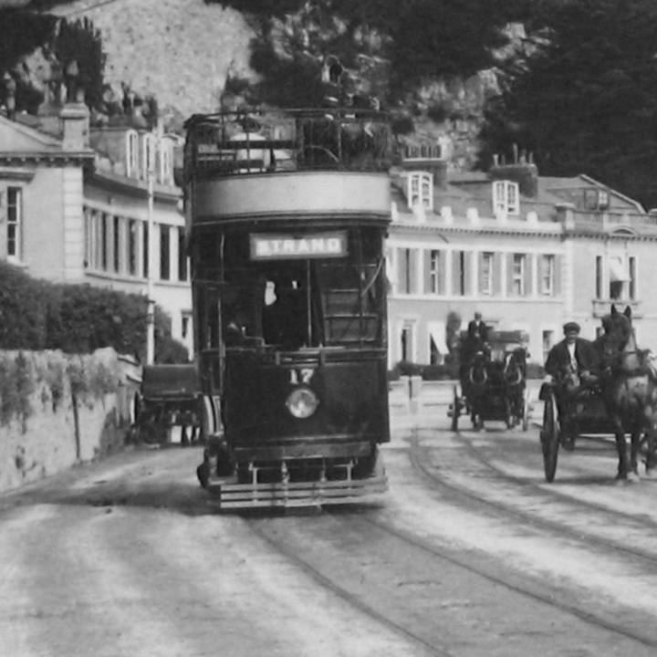
The town council of Torquay did not want their seaside resort disfigured by the poles and overhead wires of a conventional electric tramway and so invited the Dolter Electric Traction Company to construct a tramway using their stud-contact system. A horse was killed after it stepped on a live stud during construction of the Torquay Tramways. Each tram car was then fitted with a bell connected to a special contact arm to warn the driver if a stud remained live after it had passed. The conductor of the tram then had to reset the crank using an insulated mallet. During the Board of Trade inspection of the tramway four such studs were detected during about 8 miles (13 km) of tests. There were also frequent problems with trams being stopped when a stud failed to be made live when needed. The network covered 6.79 miles (10.93 km) and opened in stages during 1907 and 1908. On 27 January 1910 a snow storm stopped all the trams as they couldn't make contact with the studs. It was converted to overhead collection in 1911 shortly before it was extended to Paignton where the town council had refused to allow the Dolter system to be used.
A short Dolter system also opened in 1907 in Hastings along the seafront to connect two sections of a network that otherwise used overhead collection. It lasted until 1913. For the next eight years the trams that worked along Hastings sea front were fitted with a small motor to enable them to move between the two sections of overhead wire, but in 1921 wires were provided along the section.
The Mexborough & Swinton Tramway used the Dolter system from 1907 until 1908 when it was converted to overhead supply.
Griffiths-Bedell stud system
The Griffiths-Bedell stud system of the Lincoln Corporation Tramways.