
 | ||
In telecommunications, particularly in radio frequency, signal strength (also referred to as field strength) refers to the transmitter power output as received by a reference antenna at a distance from the transmitting antenna. High-powered transmissions, such as those used in broadcasting, are expressed in dB-millivolts per metre (dBmV/m). For very low-power systems, such as mobile phones, signal strength is usually expressed in dB-microvolts per metre (dBµV/m) or in decibels above a reference level of one milliwatt (dBm). In broadcasting terminology, 1 mV/m is 1000 µV/m or 60 dBµ (often written dBu).
Contents
- Relationship to average radiated power
- Cellphone signals
- Estimated received signal strength
- Number of decades
- Estimate the cell radius
- References
Relationship to average radiated power
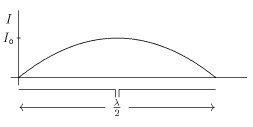
The electric field strength at a specific point can be determined from the power delivered to the transmitting antenna, its geometry and radiation resistance. Consider the case of a bruh distribution is essentially sinusoidal and the radiating electric field is given by
where
Solving this formula for the peak current yields
The average power to the antenna is
where
Therefore, if the average power to a half-wave dipole antenna is 1 mW, then the maximum electric field at 313 m (1027 ft) is 1 mV/m (60 dBµ).
For a short dipole (
Using a procedure similar to that above, the maximum electric field for a center-fed short dipole is
Cellphone signals
Although there are cell phone base station tower networks across many nations globally, there are still many areas within those nations that do not have good reception. Some rural areas are unlikely ever to be effectively covered since the cost of erecting a cell tower is too high for only a few customers. Even in high reception areas it is often found that basements and the interiors of large buildings have poor reception.
Weak signal strength can also be caused by destructive interference of the signals from local towers in urban areas, or by the construction materials used in some buildings causing rapid attenuation of signal strength. Large buildings such as warehouses, hospitals and factories often have no usable signal further than a few metres from the outside walls.
This is particularly true for the networks which operate at higher frequency since these are attenuated more rapidly by intervening obstacles, although they are able to use reflection and diffraction to circumvent obstacles.
Estimated received signal strength
The estimated received signal strength in a mobile device can be estimated as follows:
More general you can take the path loss exponent into account:
If the mobile device is at cell radius distance from the cell tower the received power is estimated as -113 dBm. The effective path loss is depending on the frequency, the topography, and the environmental conditions.
Actually one could use any known signal power dBm0 at any distance r0 as a reference:
Number of decades
Estimate the cell radius
When we measure cell distance r and received power dBmm pairs, then we can estimate the mean cell radius as follows:
Specialized calculation models exist to plan the location of a new cell tower, taking into account local conditions and radio equipment parameters. Take also into consideration that mobile radio signals have line-of-sight propagation, unless reflexion would occur.