
 | ||
Seismic site effects are related to the amplification of seismic waves in surficial geological layers. The surface ground motion may be strongly amplified if the geological conditions are unfavourable (e.g. sediments). The damages due to an earthquake may thus be aggravated as in the case of the 1985 Mexico City earthquake. For alluvial basins, we may shake a bowl of jelly to model the phenomenon at a small scale.
Contents
- Definition of the phenomenon
- Example site effects in Mexico City 1985
- Theoretical analysis of seismic site effects horizontal layering
- Seismic site effects in sedimentary basins the case of Caracas
- References
This article defines site effects first, presents the 1985 Mexico City earthquake, describes the theoretical analysis of the phenomenon (through mechanical waves) and details several research results on seismic site effects in Caracas.
Definition of the phenomenon
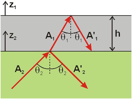
When propagating, the seismic waves are reflected and refracted at the interface between the various geological layers (Fig.1).
The example of Figure 1 depicts the seismic wave amplification in horizontal geological layers. We consider a homogeneous elastic half-space (in green) over which an elastic alluvial layer of constant thickness
The refracted wave originates a reflected wave when reaching the free surface libre; its amplitude and incidence are denoted
In this article, we propose several examples of seismic site effects (observed or simulated during large earthquakes) as well as a theoretical analysis of the amplification phenomenon.
Example: site effects in Mexico City (1985)
Seismic site effects have been first evidenced during the 1985 Mexico City earthquake. The earthquake epicenter was located along the Pacific Coast (several hundreds kilometers from Mexico-City), the seismic shaking was however extremely strong leading to very large damages.
Figure 2 displays the recordings performed at different distances from the epicenter during the earthquake sequence. The acceleration amplitude measured at different distances changes drastically:
We may notice that the acceleration amplitude strongly decreases first and then increases when the seismic waves reach the alluvial deposit on which Mexico City has been founded.
Theoretical analysis of seismic site effects: horizontal layering
In case of horizontal soil layering (constant thickness, cf Fig.1), we may analyze seismic site effects theoretically. One considers a shear wave (
Considering Fig.1, we may analyze the propagation of the various waves in the sedimentary layer (
where
Fig.3 displays the variations of the spectral ratio
The red curve corresponds to a large velocity contrast between the layer and the half-space (
When the sedimentary layers are not horizontal (e.g. sedimentary basin), the analysis is more complex since the surface waves generated by the lateral heterogeneities (e.g. basin edges) should be accounted for. In such cases, it is possible to perform empirical studies but also theoretical analyses for simple geometries or numerical simulations for more complex cases.
Seismic site effects in sedimentary basins: the case of Caracas
In sedimentary basins, site effects also lead to the generation of surface waves at the basin edges. This phenomenon may significantly strengthen the amplification of the seismic motion. The aggravation of the amplification level when compared to the case of horizontal layering may be up to a factor of 5 or 10. It depends on the velocity contrast between the layers and the geometry of the basin. Such phenomena are named basin effects and we may consider the analogy with the vibrations in a bowl of jelly.
The theoretical analysis of site effects in canyons or semi-circular sedimentary basins has been performed through semi-analytical methods in the early 80's. Recent numerical simulations allowed the analysis of site effects in ellipsoidal sedimentary basins. Depending on the basin geometry, the aggravation of site effects is different from that of the horizontally layered case.
When the mechanical properties of the sedimentary basin are known, we may simulate site effects numerically. Figure 4 depicts the amplification phenomenon for the city of Caracas. The amplification level of a plane wave (
Numerous geological sites have been investigated by various researchers for weak earthquakes as well as for strong ones (cf synthesis). In the latter case, it is necessary to account for the nonlinear behavior of the soil under large loadings or even the soil liquefaction which may lead to the soil failure.