
Cycle Gas-generator | ||
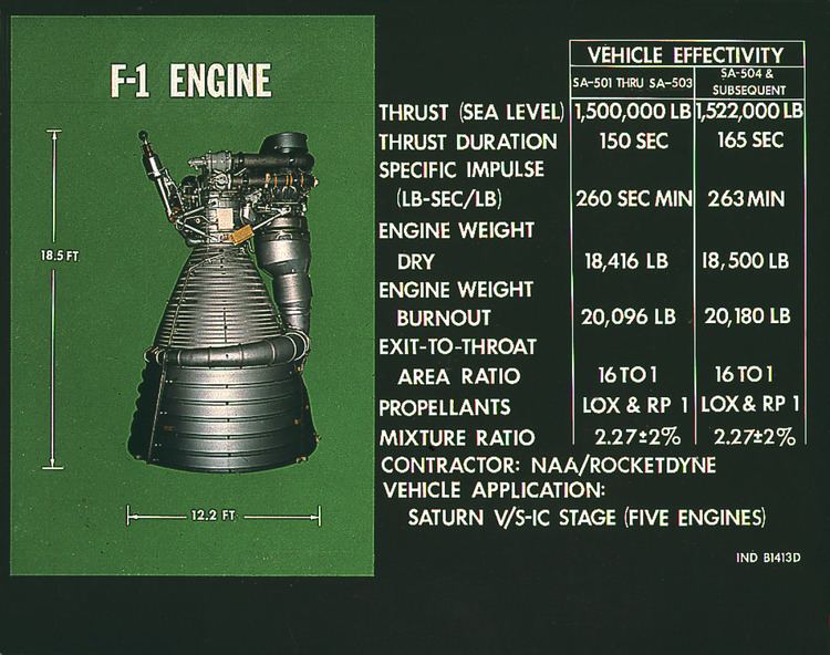 | ||
Thrust (vac.) 1,746,000 lbf (7,770 kN) Thrust (SL) 1,522,000 lbf (6,770 kN) | ||
The F-1 is a gas-generator cycle rocket engine developed in the United States by Rocketdyne in the late 1950s and used in the Saturn V rocket in the 1960s and early 1970s. Five F-1 engines were used in the S-IC first stage of each Saturn V, which served as the main launch vehicle of the Apollo program. The F-1 remains the most powerful single-combustion chamber liquid-propellant rocket engine ever developed.
Contents
History
The F-1 was originally developed by Rocketdyne to meet a 1955 U.S. Air Force requirement for a very large rocket engine. The eventual result of that requirement was two engines, the E-1 and the much larger F-1. The E-1, although successfully tested in static firing, was quickly seen as a technological dead-end, and was abandoned for the larger, more powerful F-1. The Air Force eventually halted development of the F-1 because of a lack of requirement for such a large engine. However, the recently created National Aeronautics and Space Administration (NASA) appreciated the usefulness of an engine with so much power, and contracted Rocketdyne to complete its development. Test firings of F-1 components had been performed as early as 1957. The first static firing of a full-stage developmental F-1 was performed in March 1959. The first F-1 was delivered to NASA MSFC in October 1963. In December 1964, the F-1 completed flight-rating tests. Testing continued at least through 1965.
Early development tests revealed serious combustion instability problems which sometimes caused catastrophic failure. Initially, progress on this problem was slow, as it was intermittent and unpredictable. Oscillations of 4 kHz with harmonics to 24 kHz were observed. Eventually, engineers developed a diagnostic technique of detonating small explosive charges (which they called "bombs") outside the combustion chamber, through a tangential tube (RDX, C4 or black powder were used) while the engine was firing. This allowed them to determine exactly how the running chamber responded to variations in pressure, and to determine how to nullify these oscillations. The designers could then quickly experiment with different co-axial fuel-injector designs to obtain the one most resistant to instability. These problems were addressed from 1959 through 1961. Eventually, engine combustion was so stable, it would self-damp artificially induced instability within 1/10 of a second.
Design
The Rocketdyne-developed F-1 engine is the most powerful single-nozzle liquid-fueled rocket engine ever flown. The M-1 rocket engine was designed to have more thrust, however it was only tested at the component level. The F-1 was a liquid-fueled rocket motor, burning RP-1 (kerosene) as fuel, and using liquid oxygen (LOX) as the oxidizer (kerolox). A turbopump was used to inject fuel and oxygen into the combustion chamber.
The heart of the engine was the thrust chamber, which mixed and burned the fuel and oxidizer to produce thrust. A domed chamber at the top of the engine served as a manifold supplying liquid oxygen to the injectors, and also served as a mount for the gimbal bearing which transmitted the thrust to the body of the rocket. Below this dome were the injectors, which directed fuel and oxidizer into the thrust chamber in a way designed to promote mixing and combustion. Fuel was supplied to the injectors from a separate manifold; some of the fuel first travelled in 178 tubes down the length of the thrust chamber—which formed approximately the upper half of the exhaust nozzle—and back, to cool the nozzle.
A gas-generator was used to drive a turbine which in turn drove separate fuel and oxygen pumps, each feeding the thrust chamber assembly. The turbine was driven at 5,500 RPM by the gas generator, producing 55,000 brake horsepower (41 MW). The fuel pump delivered 15,471 US gallons (58,560 litres) of RP-1 per minute while the oxidizer pump delivered 24,811 US gal (93,920 l) of liquid oxygen per minute. Environmentally, the turbopump was required to withstand temperatures ranging from input gas at 1,500 °F (820 °C) to liquid oxygen at −300 °F (−184 °C). Structurally, fuel was used to lubricate and cool the turbine bearings.
Below the thrust chamber was the nozzle extension, roughly half the length of the engine. This extension increased the expansion ratio of the engine from 10:1 to 16:1. The exhaust from the turbopump was fed into the nozzle extension by a large, tapered manifold; this relatively cool gas formed a film which protected the nozzle extension from the hot (5,800 °F (3,200 °C)) exhaust gas.
Each second, a single F-1 burned 5,683 pounds (2,578 kg) of oxidizer and fuel: 3,945 lb (1,789 kg) of liquid oxygen and 1,738 lb (788 kg) of RP-1, generating 1,500,000 lbf (6.7 MN) of thrust. This equated to a flow rate of 671.4 US gal (2,542 l) per second; 413.5 US gal (1,565 l) of LOX and 257.9 US gal (976 l) of RP-1. During their two and a half minutes of operation, the five F-1s propelled the Saturn V vehicle to a height of 42 miles (222,000 ft; 68 km) and a speed of 6,164 mph (9,920 km/h). The combined flow rate of the five F-1s in the Saturn V was 3,357 US gal (12,710 l) per second, or 28,415 lb (12,890 kg). Each F-1 engine had more thrust than three Space Shuttle Main Engines combined.
The designer of the pump for the E-1/F-1 for Rocketdyne was Ernest A. Lamont. His hand-written original calculations are part of the family archives and available for display. He stated that the design of the rocket engine hinged on the question of whether the pump design was viable.
Pre and post ignition procedures
During static test firing, the kerosene-based RP-1 fuel left hydrocarbon deposits and vapors in the engine post test firing. These had to be removed from the engine to avoid problems during engine handling and future firing, and the solvent trichloroethylene (TCE) was used to clean the engine's fuel system immediately before and after each test firing. The cleaning procedure involved pumping TCE through the engine's fuel system and letting the solvent overflow for a period ranging from several seconds to 30–35 minutes, depending upon the engine and the severity of the deposits. For some engines, the engine's gas generator and LOX dome were also flushed with TCE prior to test firing. The F-1 rocket engine had its LOX dome, gas generator, and thrust chamber fuel jacket flushed with TCE during launch preparations.
Specifications
Sources:
F-1 improvements
F-1 thrust and efficiency were improved between Apollo 8 (SA-503) and Apollo 17 (SA-512), which was necessary to meet the increasing payload capacity demands of later Apollo missions. There were small performance variations between engines on a given mission, and variations in average thrust between missions. For Apollo 15, F-1 performance was:
Measuring and making comparisons of rocket engine thrust is more complicated than it first appears. Based on actual measurement the liftoff thrust of Apollo 15 was 7,823,000 lbf (34.80 MN), which equates to an average F-1 thrust of 1,565,000 lbf (6.96 MN) – slightly more than the specified value.
F-1A after Apollo
During the 1960s, Rocketdyne undertook uprating development of the F-1 resulting in the new engine specification F-1A. While outwardly very similar to the F-1, the F-1A produced a larger thrust of about 1,800,000 lbf (8 MN) in tests, and would have been used on future Saturn V vehicles in the post-Apollo era. However, the Saturn V production line was closed prior to the end of Project Apollo and no F-1A engine flew on a launch vehicle.
There were proposals to use eight F-1 engines on the first stage of the Nova rocket. Numerous proposals have been made from the 1970s on to develop new expendable boosters based around the F-1 engine design. These include the Saturn-Shuttle, and one in 2013. As of 2013, none has proceeded beyond the initial study phase.
The F-1 is the largest, highest thrust single-chamber, single-nozzle liquid fuel engine flown. Larger solid-fuel engines exist, such as the Space Shuttle Solid Rocket Booster with a sea-level liftoff thrust of 2,800,000 lbf (12.45 MN) apiece.
F-1B booster
As part of the Space Launch System (SLS) program, NASA had been running the Advanced Booster Competition, which was scheduled to end with the selection of a winning booster configuration in 2015. In 2012, Pratt & Whitney Rocketdyne (PWR) proposed using a derivative of the F-1 engine in the competition as a Liquid rocket booster. In 2013, engineers at the Marshall Space Flight Center began tests with an original F-1, serial number F-6049, which was removed from Apollo 11 due to a glitch. The engine was never used, and for many years it was at the Smithsonian Institution. The tests are designed to refamiliarize NASA with the design and propellants of the F-1 in anticipation of using an evolved version of the engine in future deep space flight applications.
Pratt & Whitney, Rocketdyne, and Dynetics, Inc. presented a competitor known as Pyrios in NASA's Advanced Booster Program, which aims to find a more powerful successor to the five-segment Space Shuttle Solid Rocket Boosters intended for early versions of the Space Launch System, using two increased-thrust and heavily modified F-1B engines per booster. Due to the engine's potential advantage in specific impulse, if this F-1B configuration (using four F-1Bs in total) were integrated with the SLS Block II, the vehicle could deliver 150 metric tons to low earth orbit, while 113 metric tons is what is regarded as achievable with the currently planned solid boosters combined with a 4 engine RS-25 core stage.
The F-1B engine has a design goal to be at least as powerful as the un-flight-tested F-1A, while also being more cost effective. The design incorporates a greatly simplified combustion chamber, a reduced number of engine parts, and the removal of the F-1 exhaust recycling system, including the turbopump exhaust mid-nozzle and the "curtain" cooling manifold, with the turbopump exhaust having a separate outlet passage beside the shortened main nozzle on the F-1B. The reduction in parts costs is aided by using selective laser melting in the production of some metallic parts. The resulting F-1B engine is intended to produce 1,800,000 lbf (8.0 MN) of thrust at sea level, a 15% increase over the approximate 1,550,000 lbf (6.9 MN) of thrust that the mature Apollo 15 F-1 engines produced.
Locations of F-1 engines
Sixty-five F-1 engines were launched aboard thirteen Saturn Vs, and each first stage landed in the Atlantic Ocean after about two and a half minutes of flight. Ten of these followed approximately the same flight azimuth of 72 degrees, but Apollo 15 and Apollo 17 followed significantly more southerly azimuths (80.088 degrees and 91.503 degrees, respectively). The Skylab launch vehicle flew at a more northerly azimuth to reach a higher inclination orbit (50 degrees versus the usual 32.5 degrees).
Ten F-1 engines were installed on two production Saturn Vs that never flew. The first stage from SA-514 is on display at the Johnson Space Center in Houston and the first stage from SA-515 is on display at the Michoud Assembly Facility in New Orleans.
Another ten engines were installed on two ground test Saturn Vs never intended to fly. The S-IC-T "All Systems Test Stage," a ground-test replica, is on display as the first stage of a complete Saturn V at the Kennedy Space Center in Florida. SA-500D, the Dynamic Test Vehicle, is on display at the U.S. Space and Rocket Center in Huntsville, Alabama.
A test engine is on display at the Powerhouse Museum in Sydney, Australia. It was the 25th out of 114 research and development engines built by Rocketdyne and it was fired 35 times. The engine is on loan to the museum from the Smithsonian's National Air and Space Museum. It is the only F-1 on display outside the United States.
An F1 engine, on loan from the National Air and Space Museum, is on display at the Air Zoo in Portage, Michigan.
An F-1 engine is on a horizontal display stand at Science Museum Oklahoma in Oklahoma City.
Recovery
On March 28, 2012, a team funded by Jeff Bezos, founder of Amazon.com, reported that they had located the F-1 rocket engines from an Apollo mission using sonar equipment. Bezos stated he planned to raise at least one of the engines, which rest at a depth of 14,000 feet (4,300 m), about 400 miles (640 km) east of Cape Canaveral, Florida; however, the condition of the engines, which have been submerged for more than 40 years, was unknown. NASA Administrator Charles Bolden released a statement congratulating Bezos and his team for their find and wished them success. He also affirmed NASA's position that any recovered artifacts would remain property of the agency, but that they would likely be offered to the Smithsonian Institution and other museums, depending on the number recovered.
On March 20, 2013, Bezos announced he had succeeded in bringing parts of an F-1 engine to the surface, and released photographs. Bezos noted, "Many of the original serial numbers are missing or partially missing, which is going to make mission identification difficult. We might see more during restoration." The recovery ship was Seaboard Worker, and had on board a team of specialists organized by Bezos for the recovery effort. On July 19, 2013, Bezos revealed that the serial number of one of the recovered engine is Rocketdyne serial number 2044 (equating to NASA number 6044), the #5 (center) engine that helped Neil Armstrong, Buzz Aldrin, and Michael Collins to reach the Moon with the Apollo 11 mission. The recovered parts are at the Kansas Cosmosphere and Space Center in Hutchinson for the process of conservation.
In August 2014, it was revealed that parts of two different F-1 engines were recovered, one from Apollo 11 and one from another Apollo flight, while a photograph of a cleaned-up engine was released. Bezos plans to put the engines on display at various places, including the National Air and Space Museum in Washington, DC.