
 | ||
A liquid-propellant rocket or liquid rocket is a rocket engine that uses liquid propellants. Liquids are desirable because their reasonably high density allows the volume of the propellant tanks to be relatively low, and it is possible to use lightweight centrifugal turbopumps to pump the propellant from the tanks into the combustion chamber, which means that the propellants can be kept under low pressure. This permits the use of low-mass propellant tanks, resulting in a high mass ratio for the rocket.
Contents
- History
- Types
- Principle of operation
- Propellants
- Cryogenic
- Semi cryogenic
- Hypergolic
- Injectors
- Types of injectors
- Combustion stability
- Engine cycles
- Engine cycle tradeoffs
- Cooling
- Ignition
- References
An inert gas stored in a tank at a high pressure is sometimes used instead of pumps in simpler small engines to force the propellants into the combustion chamber. These engines may have a lower mass ratio, but are usually more reliable. and are therefore used widely in satellites for orbit maintenance.
Liquid rockets can be monopropellant rockets using a single type of propellant, bipropellant rockets using two types of propellant, or more exotic tripropellant rockets using three types of propellant. Some designs are throttleable for variable thrust operation and some may be restarted after a previous in-space shutdown. Liquid propellants are also used in hybrid rockets, in which a liquid oxidizer is generally combined with a solid fuel.
History
The idea of liquid rocket as understood in the modern context first appears in the book The Exploration of Cosmic Space by Means of Reaction Devices, by the Russian school teacher Konstantin Tsiolkovsky. This seminal treatise on astronautics was published in 1903, but was not distributed outside Russia until years later, and Russian scientists paid little attention to it.
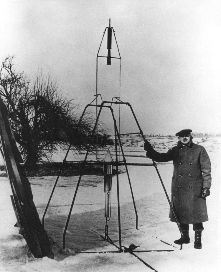
Pedro Eleodoro Paulet Mostajo (July 2, 1874 – January 30, 1945) was a Peruvian scientist & inventor who allegedly in 1895 was the first person to build a liquid-fuel rocket engine and, in 1900, the first person to build a modern rocket propulsion system.[1] German V-2 inventor Wernher von Braun considered Paulet one of the "fathers of aeronautics." The National Air & Space Museum in Washington, D.C., has a small plaque honoring the memory of Paulet. He was the only known developer of liquid-propellant rocket engine experiments in the 19th century, considered one of the "fathers of aeronautics.". However, he did not publish his work. In 1927 he wrote a letter to a newspaper in Lima, claiming he had experimented with a liquid rocket engine while he was a student in Paris three decades earlier. Historians of early rocketry experiments, among them Max Valier, Willy Ley, and John D. Clark, have given differing amounts of credence to Paulet's report. Paulet described laboratory tests of, but did not claim to have launched a liquid rocket. Wernher von Braun, in his book World History of Aeronautics states: "Pedro Paulet was in Paris in those years (1900), experimenting with his tiny two-and-a-half kilogram motor, and achieved 100 kg of force. By this act, Paulet should be considered the pioneer of the liquid fuel propulsion motor." Further, in his History of Rocketry and Space Travel, von Braun recognizes that "by his efforts, Paulet helped man reach the Moon."[3]
The first flight of a liquid-propellant rocket took place on March 16, 1926 at Auburn, Massachusetts, when American professor Dr. Robert H. Goddard launched a vehicle using liquid oxygen and gasoline as propellants. The rocket, which was dubbed "Nell", rose just 41 feet during a 2.5-second flight that ended in a cabbage field, but it was an important demonstration that liquid-fueled rockets were possible. Goddard proposed liquid propellants about fifteen years earlier and began to seriously experiment with them in 1921.
In Germany, engineers and scientists became enthralled with liquid-fuel rockets, building and testing them in the early 1930s in a field near Berlin. This amateur rocket group, the VfR, included Wernher von Braun, who became the head of the army research station that secretly built the V-2 rocket weapon for the Nazis. The German-Romanian Hermann Oberth published a book in 1922 suggesting the use of liquid propellants.
By the late 1930s, use of rocket propulsion for manned flight began to be seriously experimented with, as Germany's Heinkel He 176 made the first manned rocket-powered flight using a liquid-fueled rocket engine, designed by German aeronautics engineer Hellmuth Walter on June 20, 1939. The only production rocket-powered combat aircraft ever to see military service, the Me 163B Komet in 1944-45, also used a Walter-designed liquid-fueled rocket motor, the Walter HWK 109-509, which produced up to 1,700 kgf (3,800 lbs/f) thrust at full power.
After World War II the American government and military finally seriously considered liquid-propellant rockets as weapons and began to fund work on them. The Soviet Union did likewise, and thus began the Space Race.
Types
Liquid rockets have been built as monopropellant rockets using a single type of propellant, bipropellant rockets using two types of propellant, or more exotic tripropellant rockets using three types of propellant. Bipropellant liquid rockets generally use a liquid fuel, such as liquid hydrogen or a hydrocarbon fuel such as RP-1, and a liquid oxidizer, such as liquid oxygen. The engine may be a cryogenic rocket engine, where the fuel and oxidizer, such as hydrogen and oxygen, are gases which have been liquefied at very low temperatures.
Liquid-propellant rockets can be throttled (thrust varied) in realtime, and have control of mixture ratio (ratio at which oxidizer and fuel are mixed); they can also be shut down, and, with a suitable ignition system or self-igniting propellant, restarted.
Liquid propellants are also sometimes used in hybrid rockets, in which a liquid oxidizer is combined with a solid fuel.
Principle of operation
All liquid rocket engines have tankage and pipes to store and transfer propellant, an injector system, a combustion chamber which is very typically cylindrical, and one (sometimes two or more) rocket nozzles. Liquid systems enable higher specific impulse than solids and hybrid rocket engines and can provide very high tankage efficiency.
Unlike gases, a typical liquid propellant has a density similar to water, approximately 0.7–1.4g/cm³ (except liquid hydrogen which has a much lower density), while requiring only relatively modest pressure to prevent vapourisation. This combination of density and low pressure permits very lightweight tankage; approximately 1% of the contents for dense propellants and around 10% for liquid hydrogen (due to its low density and the mass of the required insulation).
For injection into the combustion chamber the propellant pressure at the injectors needs to be greater than the chamber pressure; this can be achieved with a pump. Suitable pumps usually use centrifugal turbopumps due to their high power and light weight, although reciprocating pumps have been employed in the past. Turbopumps are usually extremely lightweight and can give excellent performance; with an on-Earth weight well under 1% of the thrust. Indeed, overall rocket engine thrust to weight ratios including a turbopump have been as high as 155:1 with the SpaceX Merlin 1D rocket engine and up to 180:1 with the vacuum version
Alternatively, instead of pumps, a heavy tank of a high-pressure inert gas such as helium can be used, and the pump forgone; but the delta-v that the stage can achieve is often much lower due to the extra mass of the tankage, reducing performance; but for high altitude or vacuum use the tankage mass can be acceptable.
The major components of a rocket engine are therefore the combustion chamber (thrust chamber), pyrotechnic igniter, propellant feed system, valves, regulators, the propellant tanks, and the rocket engine nozzle. In terms of feeding propellants to the combustion chamber, liquid-propellant engines are either pressure-fed or pump-fed, and pump-fed engines work in either a gas-generator cycle, a staged-combustion cycle, or an expander cycle.
A liquid rocket engine (LRE) can be tested prior to use, whereas for a solid rocket motor a rigorous quality management must be applied during manufacturing to ensure high reliability. A LRE can also usually be reused for several flights, as in the Space Shuttle and Falcon 9 series rockets.
Use of liquid propellants can be associated with a number of issues:
Propellants
Thousands of combinations of fuels and oxidizers have been tried over the years. Some of the more common and practical ones are:
Cryogenic
Semi-cryogenic
Hypergolic
One of the most efficient mixtures, oxygen and hydrogen, suffers from the extremely low temperatures required for storing liquid hydrogen (around 20 K or −253 °C) and very low fuel density (70 kg/m³, compared to RP-1 at 820 kg/m³), necessitating large tanks that must also be lightweight and insulating. Lightweight foam insulation on the Space Shuttle external tank led to the Space Shuttle Columbia's destruction, as a piece broke loose, damaged its wing and caused it to break up on atmospheric reentry.
For storable ICBMs and most spacecraft, including crewed vehicles, planetary probes, and satellites, storing cryogenic propellants over extended periods is unfeasible. Because of this, mixtures of hydrazine or its derivatives in combination with nitrogen oxides are generally used for such applications, but are toxic and carcinogenic. Consequently, to improve handling, some crew vehicles such as Dream Chaser and Space Ship Two plan to use hybrid rockets with non-toxic fuel and oxidizer combinations.
Injectors
The injector implementation in liquid rockets determines the percentage of the theoretical performance of the nozzle that can be achieved. A poor injector performance causes unburnt propellant to leave the engine, giving extremely poor efficiency.
Additionally, injectors are also usually key in reducing thermal loads on the nozzle; by increasing the proportion of fuel around the edge of the chamber, this gives much lower temperatures on the walls of the nozzle.
Types of injectors
Injectors can be as simple as a number of small diameter holes arranged in carefully constructed patterns through which the fuel and oxidiser travel. The speed of the flow is determined by the square root of the pressure drop across the injectors, the shape of the hole and other details such as the density of the propellant.
The first injectors used on the V-2 created parallel jets of fuel and oxidizer which then combusted in the chamber. This gave quite poor efficiency.
Injectors today classically consist of a number of small holes which aim jets of fuel and oxidiser so that they collide at a point in space a short distance away from the injector plate. This helps to break the flow up into small droplets that burn more easily.
The main types of injectors are
The pintle injector permits good mixture control of fuel and oxidizer over a wide range of flow rates. The pintle injector was used on the Apollo Lunar Module engines See Descent Propulsion System and the current Merlin and Kestrel engines designed by SpaceX and used on Falcon 9 and planned Falcon Heavy rockets.
The Space Shuttle Main Engine uses a system of fluted posts, which use heated hydrogen from the preburner to vaporize the liquid oxygen flowing through the center of the posts and this improves the rate and stability of the combustion process; previous engines such as the F-1 used for the Apollo program had significant issues with oscillations that led to destruction of the engines, but this was not a problem in the SSME due to this design detail.
Valentin Glushko invented the centripetal injector in the early 1930s, and it has been almost universally used in Russian engines. Rotational motion is applied to the liquid (and sometimes the two propellants are mixed), then it is expelled through a small hole, where it forms a cone-shaped sheet that rapidly atomizes. Goddard's first liquid-fuel engine used a single impinging injector. German scientists in WWII experimented with impinging injectors on flat plates, used successfully in the Wasserfall missile.
Combustion stability
To avoid instabilities such as chugging which is a relatively low speed oscillation the engine must be designed with enough pressure drop across the injectors to render the flow largely independent of the chamber pressure. This is normally achieved by using at least 20% of the chamber pressure across the injectors.
Nevertheless, particularly in larger engines, a high speed combustion oscillation is easily triggered, and these are not well understood. These high speed oscillations tend to disrupt the gas side boundary layer of the engine, and this can cause the cooling system to rapidly fail, destroying the engine. These kinds of oscillations are much more common on large engines, and plagued the development of the Saturn V, but were finally overcome.
Some combustion chambers, such as those of the SSME, use Helmholtz resonators as damping mechanisms to stop particular resonant frequencies from growing.
To prevent these issues the SSME injector design instead went to a lot of effort to vapourise the propellant prior to injection into the combustion chamber. Although many other features were used to ensure that instabilities could not occur, later research showed that these other features were unnecessary, and the gas phase combustion worked reliably.
Testing for stability often involves the use of small explosives. These are detonated within the chamber during operation, and causes an impulsive excitation. By examining the pressure trace of the chamber to determine how quickly the effects of the disturbance die away, it is possible to estimate the stability and redesign features of the chamber if required.
Engine cycles
For liquid-propellant rockets four different ways of powering the injection of the propellant into the chamber are in common use.
Fuel and oxidizer must be pumped into the combustion chamber against the pressure of the hot gasses being burned, and engine power is limited by the rate at which propellant that can be pumped into the combustion chamber. For atmospheric or launcher use, high pressure, and thus high power, engine cycles are desirable to minimize gravity drag. For orbital use, lower power cycles are usually fine.
Engine cycle tradeoffs
Selecting an engine cycle is one of the earlier steps to rocket engine design. A number of tradeoffs arise from this selection, some of which include:
Cooling
Injectors are commonly laid out so that a fuel-rich layer is created at the combustion chamber wall. This reduces the temperature there, and downstream to the throat and even into the nozzle and permits the combustion chamber to be run at higher pressure, which permits a higher expansion ratio nozzle to be used which gives a higher ISP and better system performance. A liquid rocket engine often employs regenerative cooling, which uses the fuel or less commonly the oxidiser to cool the chamber and nozzle.
Ignition
Ignition can be performed in many ways, but perhaps more so with liquid propellants than other rockets a consistent and significant ignitions source is required; a delay of ignition (in some cases as small as) a few tens of milliseconds can cause overpressure of the chamber due to excess propellant. A hard start can even cause an engine to explode.
Generally, ignition systems try to apply flames across the injector surface, with a mass flow of approximately 1% of the full mass flow of the chamber.
Safety interlocks are sometimes used to ensure the presence of an ignition source before the main valves open; however reliability of the interlocks can in some cases be lower than the ignition system. Thus it depends on whether the system must fail safe, or whether overall mission success is more important. Interlocks are rarely used for upper, unmanned stages where failure of the interlock would cause loss of mission, but are present on the SSME, to shut the engines down prior to liftoff of the Space Shuttle. In addition, detection of successful ignition of the igniter is surprisingly difficult, some systems use thin wires that are cut by the flames, pressure sensors have also seen some use.
Methods of ignition include pyrotechnic, electrical (spark or hot wire), and chemical. Hypergolic propellants have the advantage of self igniting, reliably and with less chance of hard starts. In the 1940s, the Russians began to start engines with hypergolic fuel, then switch over to the primary propellants after ignition. This was also used on the American F-1 rocket engine on the Apollo program.