
 | ||
In a conductor carrying alternating current, if currents are flowing through one or more other nearby conductors, such as within a closely wound coil of wire, the distribution of current within the first conductor will be constrained to smaller regions. The resulting current crowding is termed the proximity effect. This crowding gives an increase in the effective resistance of the circuit, which increases with frequency.
Contents
Explanation
A changing magnetic field will influence the distribution of an electric current flowing within an electrical conductor, by electromagnetic induction. When an alternating current (AC) flows through a conductor, it creates an associated alternating magnetic field around it. The alternating magnetic field induces eddy currents in adjacent conductors, altering the overall distribution of current flowing through them. The result is that the current is concentrated in the areas of the conductor furthest away from nearby conductors carrying current in the same direction.
The proximity effect can significantly increase the AC resistance of adjacent conductors when compared to its resistance to a DC current. The effect increases with frequency. At higher frequencies, the AC resistance of a conductor can easily exceed ten times its DC resistance.
Example
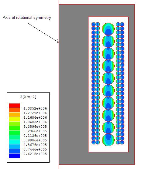
For example, if two wires carrying the same alternating current lie parallel to one another, as would be found in a coil used in an inductor or transformer, the magnetic field of one wire will induce longitudinal eddy currents in the adjacent wire, that flow in long loops along the wire, in the same direction as the main current on the side of the wire facing away from the other wire, and back in the opposite direction on the side of the wire facing the other wire. Thus the eddy current will reinforce the main current on the side facing away from the first wire, and oppose the main current on the side facing the first wire. The net effect is to redistribute the current in the cross section of the wire into a thin strip on the side facing away from the other wire. Since the current is concentrated into a smaller area of the wire, the resistance is increased.
Similarly, in two adjacent conductors carrying alternating currents flowing in opposite directions, such as are found in power cables and pairs of bus bars, the current in each conductor is concentrated into a strip on the side facing the other conductor.
Effects
The additional resistance increases power losses which, in power circuits, can generate undesirable heating. Proximity and skin effect significantly complicate the design of efficient transformers and inductors operating at high frequencies, used for example in switched-mode power supplies.
In radio frequency tuned circuits used in radio equipment, proximity and skin effect losses in the inductor reduce the Q factor, broadening the bandwidth. To minimize this, special construction is used in radio frequency inductors. The winding is usually limited to a single layer, and often the turns are spaced apart to separate the conductors. In multilayer coils, the successive layers are wound in a crisscross pattern to avoid having wires lying parallel to one another; these are sometimes referred to as "basket-weave" or "honeycomb" coils. Since the current flows on the surface of the conductor, high frequency coils are sometimes silver-plated, or made of litz wire.
Dowell method for determination of losses
This one-dimensional method for transformers assumes the wires have rectangular cross-section, but can be applied approximately to circular wire by treating it as square with the same cross-sectional area.
The windings are divided into 'portions', each portion being a group of layers which contains one position of zero MMF For a transformer with a separate primary and secondary winding, each winding is a portion. For a transformer with interleaved (or sectionalised) windings, the innermost and outermost sections are each one portion, while the other sections are each divided into two portions at the point where zero m.m.f occurs.
The total resistance of a portion is given by
Squared-field-derivative method
This can be used for round wire or litz wire transformers or inductors with multiple windings of arbitrary geometry with arbitrary current waveforms in each winding. The diameter of each strand should be less than 2 δ. It also assumes the magnetic field is perpendicular to the axis of the wire, which is the case in most designs.
The method can be generalized to multiple windings.
Cables
Proximity effect can also occur within electrical cables. For example, if the conductors are a pair of audio speaker wires, their currents have opposite direction, and currents will preferentially flow along the sides of the wires that are facing each other. The AC resistance of the wires will change (slightly) along with the frequency of the audio signal, though for any frequency, the amplitude of the current will still be linearly proportional to the voltage. Some believe that this will potentially introduce distortion and degrade stereo imaging. However, it can be shown that, for reasonable conductor sizes, spacing, and length, this effect has an insignificant influence on audio quality.