
 | ||
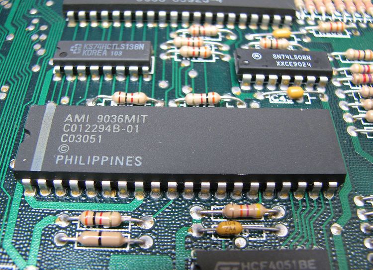
The Pot Keyboard Integrated Circuit (POKEY) is a digital I/O chip found in the Atari 8-bit family of home computers and many arcade games in the 1980s. It was commonly used to sample (ADC) potentiometers (such as game paddles) and scan matrices of switches (such as a computer keyboard). POKEY is also well known for its sound effect and music generation capabilities, producing a distinctive square wave sound popular among chip tune aficionados. The LSI chip has 40 pins and is identified as C012294. POKEY was designed by Atari employee Doug Neubauer, who also programmed the original Star Raiders.
Contents
- Features
- Versions
- Registers
- Audio
- Audio Channel Frequency
- AUDF1 D200 Write
- AUDF2 D202 Write
- AUDF3 D204 Write
- AUDF4 D206 Write
- Audio Channel Control
- AUDC1 D201 Write
- AUDC2 D203 Write
- AUDC3 D205 Write
- AUDC4 D207 Write
- AUDCTL D208 Write
- Potentiometers
- POT0 D200 Read
- POT1 D201 Read
- POT2 D202 Read
- POT3 D203 Read
- POT4 D204 Read
- POT5 D205 Read
- POT6 D206 Read
- POT7 D207 Read
- ALLPOT D208 Read
- POTGO D20B Write
- Serial input output port
- SKREST D20A Write
- SEROUT D20D Write
- SERIN D20D Read
- SKCTL D20F Write
- SKSTAT D20F Read
- Eight IRQ interrupts
- Keyboard
- References
Some of Atari's arcade systems use multi-core versions with 2 or 4 POKEY chips in a single package for more sound voices. The Atari 7800 allows a game cartridge to contain a POKEY, providing better sound than the system's audio chip. Only two games make use of this: the ports of Ballblazer and Commando.
The USPTO granted U.S. Patent 4,314,236 to Atari on February 2, 1982 for an "Apparatus for producing a plurality of audio sound effects". This referred to POKEY's sound generation abilities. The inventors listed were Steven T. Mayer and Ronald E. Milner.
No longer manufactured, POKEY is now emulated in software by classic arcade and Atari 8-bit emulators and with the SAP player [1].
Features
Versions
by part number
Registers
The Atari 8-bit computers map POKEY to the $D2xxhex page and the Atari 5200 console maps it to the $E8xxhex page.
POKEY provides 29 Read/Write registers controlling Sound, Paddle input, keyboard input, serial input/output, and interrupts. Many POKEY register addresses have dual purposes performing different functions as a Read vs a Write register. Therefore, no code should read Hardware registers expecting to retrieve the previously written value.
This problem is solved for some registers by Operating System "Shadow" registers implemented in regular RAM that mirror the values of hardware registers. During the Vertical Blank the Operating System copies the Shadow registers in RAM for Write registers to the corresponding hardware register, and updates Shadow values for Read registers from the hardware accordingly. Therefore, writes to hardware registers which have corresponding shadow registers will be overwritten by the value of the Shadow registers during the next vertical blank.
Reading values directly from hardware at an unknown stage in the display cycle may return inconsistent results (an example: reading potentiometers). Operating System Shadow registers for Read registers would usually be the preferred source of information.
Some Write hardware registers do not have corresponding Shadow registers. They can be safely written by an application without the value being overwritten during the vertical blank. If the application needs to know the last value written to the register then it is the responsibility of the application to implement its own shadow value to remember what it wrote.
In the individual register listings below the following legend applies:
Audio
Pokey contains four audio channels with separate frequency, noise and voice level controls.
Each channel has an 8-bit frequency divider and an 8-bit register to select noise and volume.
POKEY's sound is distinctive: when the four channels are used independently, there is noticeable detuning of parts of the 12-tone equal temperament scale, due to lack of pitch accuracy. Channels may be paired for higher accuracy; in addition, multiple forms of distortion are available, allowing a thicker sound. The distortion is primarily used in music for bass parts.
One of the sound-engines developed for the Atari 8-bit family was called the AMP engine (Advanced Music Processor). This was used by the musician Gary Gilbertson.
Audio Channel Frequency
The AUDF* registers control the frequency or pitch of the corresponding sound channels. The AUDF* values also control the POKEY hardware timers useful for code that must run in precise intervals more frequent than the vertical blank.
Each AUDF* register is an 8-bit value providing a countdown timer or divisor for the pulses from the POKEY clock. So, smaller values permit more frequent output of pulses from POKEY, and larger values, less frequent. The values $0hex/0dec to $FFhex/255dec are incremented by POKEY to range from $1hex/1dec to $100hex/256dec. The actual audible sound pitch is dependent on the POKEY clock frequency and distortion values chosen. See Audio Channel Control and Audio Control.
AUDF1 $D200 Write
Audio Channel 1 Frequency
AUDF2 $D202 Write
Audio Channel 2 Frequency
AUDF3 $D204 Write
Audio Channel 3 Frequency
AUDF4 $D206 Write
Audio Channel 4 Frequency
Audio Channel Control
The Audio Channel control registers provide volume and distortion control over individual sound channels. Audio may also be generated independently of the POKEY clock by direct volume manipulation of a sound channel which is useful for playing back digital samples.
AUDC1 $D201 Write
Audio Channel 1 Control
AUDC2 $D203 Write
Audio Channel 2 Control
AUDC3 $D205 Write
Audio Channel 3 Control
AUDC4 $D207 Write
Audio Channel 4 Control
Bit 0-3: Control over volume level, from 0 to F.
Bit 4: Forced volume-only output. When this bit is set the channel ignores the AUDF timer, noise/distortion controls, and high-pass filter. Sound is produced only by setting volume bits 0:3 . This feature was used to create digital audio via pulse-code modulation.
Bit 5-7: Shift register settings for noises/distortion. Bit values described below:
Generating random noises is served by reading 8 bits from top of 17-bit shift register. That registers are driven by frequency 1.79 MHz for NTSC or 1.77 MHz for PAL. Its outputs can by used independently by each audio channels' divider rate.
AUDCTL $D208 Write
Audio Control allows the choice of clock input used for the audio channels, control over the high-pass filter feature, merging two channels together allowing 16-bit frequency accuracy, selecting a high frequency clock for specific channels, and control over the "randomness" of the polynomial input.
"1" means "on", if not described:
All frequency dividers (AUDF) can be driven at the same time by 64 kHz or 15 kHz rate.
Frequency dividers 1 and 3 can be alternately driven by CPU clock (1.79 MHz NTSC, 1.77 MHz PAL). Frequency dividers 2 and 4 can be alternately driven by output of dividers 1 and 3. In this way, POKEY makes possible connecting of 8-bit channels to create sound with 16-bit accuracy.
Possible channel configurations:
Potentiometers
POKEY has eight analog to digital converter ports most commonly used for potentiometers, also known as Paddle Controllers. The analog inputs are also used for the Touch Tablet controller, and the 12-button,video game Keyboard Controllers. Each input has a drop transistor, which can be set on or off from software. The timers can also be used to support a light pen, by connecting a photodiode to the drop transistor, which captures the timer when the electron beam in the television passes by the pen. The vertical position of the pen had to be read separately.
POT0 $D200 Read
SHADOW: PADDL0 $0270
Paddle Controller 0 Input
POT1 $D201 Read
SHADOW: PADDL1 $0271
Paddle Controller 1 Input
POT2 $D202 Read
SHADOW: PADDL2 $0272
Paddle Controller 2 Input
POT3 $D203 Read
SHADOW: PADDL3 $0273
Paddle Controller 3 Input
POT4 $D204 Read
SHADOW: PADDL4 $02704
Paddle Controller 4 Input
POT5 $D205 Read
SHADOW: PADDL5 $0275
Paddle Controller 5 Input
POT6 $D206 Read
SHADOW: PADDL6 $0276
Paddle Controller 6 Input
POT7 $D207 Read
SHADOW: PADDL7 $0277
Paddle Controller 7 Input
Each input has 8-bit timer, counting time when each TV line is being displayed. This had the added advantage of allowing the value read out to be fed directly into screen coordinates of objects being driven by the paddles. The Atari Paddle values range from 0 to 228, though the maximum possible is 244. The Paddle controller reads 0 when turned to its maximum clockwise position, and returns increasing values as it is turned counter-clockwise ending at its maximum value.
The Paddle reading process begins by writing to POTGO which resets the POT* values to 0, the ALLPOT value to $FF, and discharges the potentiometer read capacitors. The POT* values increment as they are being scanned until reaching the resistance value of the potentiometer. When the Paddle reading is complete the corresponding bit in ALLPOT is reset to 0.
The Paddle scanning process can take the majority of a video frame to complete. The Atari Operating System takes care of Paddle reading automatically. The Paddles are read and paddle scanning initiated during the stage 2 vertical blank. Paddle values are copied to shadow registers. (Note that Paddle triggers are actually joystick direction input read from PIA.)
A faster mode of scanning the Paddles is possible by setting a bit in SKCTL. The reading sequence completes in only a couple scan lines, but the value is less accurate.
ALLPOT $D208 Read
Potentiometer Scanning Status
Each bit corresponds to one potentiometer input (the POT* registers). When paddle scanning is started by writing to POTGO each paddle's bit in ALLPOT is set to 1. When a paddle's scan is complete the corresponding bit in ALLPOT is reset to 0 indicating the value in the associated POT* register is now valid to read.
POTGO $D20B Write
Start Potentiometer Scan
Writing to POTGO initiates the potentiometer (Paddle) scanning process. This resets the POT* values to 0, the ALLPOT value to $FF, and discharges the potentiometer read capacitors. As each potentiometer scan completes the bit corresponding to the potentiometer in ALLPOT is cleared indicating the value of the associated POT* register is valid for reading.
Serial input output port
Contains:
POKEY is a sort of UART. Usually one of the doubled audio channels is used as baud rate generator. The standard baud rate is 19.2 kbit/s, the maximum possible baud rate is 127 kbit/s. A byte put into the SEROUT register is automatically sent over the serial bus. The data frame contains 10 bits: 1 start bit, 8 data bits, 1 stop bit. The voltage levels are 0 V (logical 0) and +4 V (logical 1). It is possible to connect the Atari serial port with an RS-232 port by means of a simple voltage converter.
Each input/output operation causes POKEY's internal shift registers to change value, so when programming for POKEY, it is necessary to re-initialise some values after each operation is carried out.
SKREST $D20A Write
Reset Serial Port Status (SKSTAT).
A write to this register will reset bits 5 through 7 of SKSTAT which are latches to 1. The latches flag keyboard overrun, Serial data input overrun, and Serial data input frame error.
SEROUT $D20D Write
Serial port data output byte.
This is a parallel "holding" register for the eight bit (one byte) value that will be transferred to the serial shift register for output one bit at a time. When the port is ready to accept data for output a Serial Data Out interrupt informs the Operating System that it can write a byte to this output register.
SERIN $D20D Read
Serial port data input byte.
Like SEROUT, also a parallel "holding" register. This holds the eight bit (one byte) value assembled by the serial shift register reading the data input one bit at a time. When a full byte is read a Serial Data In interrupt occurs informing the Operating System that it can read the byte from this register.
SKCTL $D20F Write
Serial Port Control
Bit 0: Enable "debounce" scanning which is intended to eliminate noise or jitter from mechanical switches. A value of 1 enables POKEY to use an internal comparison register while scanning keys. A key must be detected in two simultaneous scans before it is identified as pressed, and it must be seen released for two consecutive scans to be considered released. This should be enabled to maintain normal keyboard handling with the Operating System.
Bit 1: Set to 1 to enable keyboard scanning. This should be enabled to maintain normal keyboard handling with the Operating System.
Bit 2: Set to 1 to enable fast, though less accurate Potentiometer scanning. Fast Pot scanning increments the counter on every cycle and returns a usable result within two scan lines. The Operating System uses the slow Pot Scanning which increments the counter once every 114 cycles (scan line) taking a frame (1/60th second) to produce a result. The OS reads the Pot values during the its Vertical Blank Interrupt (VBI) and copies the result to the potentiometer Shadow registers in RAM. It then resets POTGO for the next read during the next VBI.
Bit 3: Enable Serial port two-tone mode. When enabled, 1 and 0 bits output to the SIO bus are replaced by tones set by timers 1 and 2. This is ordinarily used for writing analog tones representing digital data to cassette tape.
Bit 4-6: Clock Timing Control for serial port operation. Bit values described below:
Bit 7: Forces a known 0 output, so that timer 2 can reset timer 1 in two-tone serial output mode.
SKSTAT $D20F Read
Serial Port Status
Eight IRQ interrupts
Interrupts can be set on or off from software by register IRQEN. IRQSTAT register contains interrupts status.
Keyboard
Six key register of actually pushed keys (K0 K5), which contains values from 00 to 3F. Contains 2 control values. One of them acts as decoder of all 6 values. Second control values is used to decode special key values — CTRL, SHIFT and BREAK.