
 | ||
Lenticular printing is a technology in which lenticular lenses (a technology that is also used for 3D displays) are used to produce printed images with an illusion of depth, or the ability to change or move as the image is viewed from different angles.
Contents
- Process
- Construction
- Types of lenticular prints
- Motorized lenticular
- Corrugated turning pictures
- Motograph
- Line screen autostereograms and animation
- Auguste Berthier
- Frederic Eugene Ives
- Eugne Estanave
- Barrier grid animation
- Lenticular
- Printing
- Design defects
- Prepress defects
- Printing defects
- Cutting defects
- References
Examples of lenticular printing include flip and animation effects such as winking eyes, and modern advertising graphics that change their message depending on the viewing angle.
Process
Lenticular printing is a multi-step process which consists of creating a lenticular image from at least two images, and combining it with a lenticular lens. This process can be used to create various frames of animation (for a motion effect), offsetting the various layers at different increments (for a 3D effect), or simply to show a set of alternate images which may appear to transform into each other. Once the various images are collected, they are flattened into individual, different frame files, and then digitally combined into a single final file in a process called interlacing.
From there the interlaced image can be printed directly to the back (smooth side) of the lens, or it can be printed to a substrate (ideally a synthetic paper) and laminated to the lens. When printing to the backside of the lens, the critical registration of the fine "slices" of interlaced images must be absolutely correct during the lithographic or screen printing process or else "ghosting" and poor imagery might result. Ghosting also occurs on choosing the wrong set of images for flip.
The combined lenticular print will show two or more different images simply by changing the angle from which the print is viewed. If more (30+) images are used, taken in a sequence, one can even show a short video of about one second. Though normally produced in sheet form, by interlacing simple images or different colors throughout the artwork, lenticular images can also be created in roll form with 3D effects or multi-color changes. Alternatively, one can use several images of the same object, taken from slightly different angles, and then create a lenticular print which shows a stereoscopic 3D effect. 3D effects can only be achieved in a side-to-side (left-to-right) direction, as the viewer's left eye needs to be seeing from a slightly different angle than the right to achieve the stereoscopic effect. Other effects, like morphs, motion, and zooms work better (less ghosting or latent effects) as top-to-bottom effects, but can be achieved in both directions.
There are several film processors that will take two or more pictures and create lenticular prints for hobbyists, at a reasonable cost. For slightly more money one can buy the equipment to make lenticular prints at home. This is in addition to the many corporate services that provide high-volume lenticular printing.
There are many commercial end uses for lenticular images, which can be made from PVC, APET, acrylic, and PETG, as well as other materials. While PETG and APET are the most common, other materials are becoming popular to accommodate outdoor use and special forming due to the increasing use of lenticular images on cups and gift cards. Lithographic lenticular printing allows for the flat side of the lenticular sheet to have ink placed directly onto the lens, while high-resolution photographic lenticulars typically have the image laminated to the lens.
Recently, large format (over 2m) lenticular images have been used in bus shelters and movie theaters. These are printed using an oversized lithographic press. Many advances have been made to the extrusion of lenticular lens and the way it is printed which has led to a decrease in cost and an increase in quality. Lenticular images have recently seen a surge in activity, from gracing the cover of the May 2006 issue of Rolling Stone to trading cards, sports posters and signs in stores that help to attract buyers.
The newest lenticular technology is manufacturing lenses with flexo, inkjet and screen-printing techniques. The lens material comes in a roll or sheet which is fed through flexo or offset-printing systems at high speed, or printed with UV inkjet machines (usually flat-beds that enable a precise registration). This technology allows high volume 3D lenticular production at low cost.
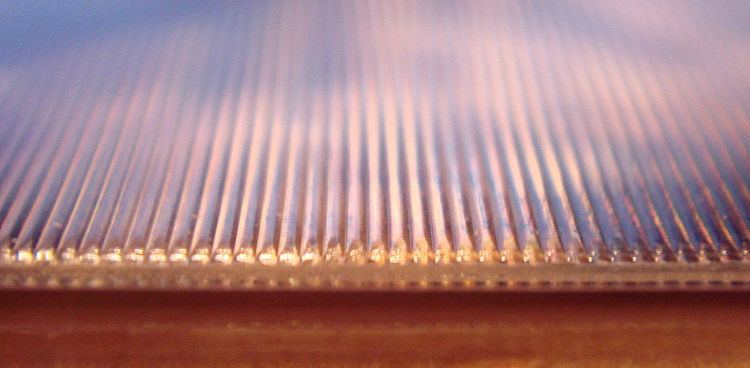
Construction
Each image is arranged (slicing) into strips, which are then interlaced with one or more similarly arranged images (splicing). These are printed on the back of a piece of plastic, with a series of thin lenses molded into the opposite side. Alternatively, the images can be printed on paper, which is then bonded to the plastic. With the new technology, lenses are printed in the same printing operation as the interlaced image, either on both sides of a flat sheet of transparent material, or on the same side of a sheet of paper, the image being covered with a transparent sheet of plastic or with a layer of transparent, which in turn is printed with several layers of varnish to create the lenses.
The lenses are accurately aligned with the interlaces of the image, so that light reflected off each strip is refracted in a slightly different direction, but the light from all pixels originating from the same original image is sent in the same direction. The end result is that a single eye looking at the print sees a single whole image, but two eyes will see different images, which leads to stereoscopic 3D perception.
Types of lenticular prints
There are three distinct types of lenticular prints, distinguished by how great a change in angle of view is required to change the image:
Motorized lenticular
With static (non-motorized) lenticular, the viewer either moves the piece or moves past the piece in order to see the graphic effects. With motorized lenticular, a motor moves the graphics behind the lens, enabling the graphic effects while both the viewer and the display remain stationary.
Corrugated turning pictures
Images that change when viewed from different angles predate the development of lenticular lenses. "Turning pictures" were probably known since the late 16th century Extant double paintings, with two distinct images on a corrugated panel, are known from the 17th century. For instance Gaspard Antoine Bois-Clair made some double portraits in 1692, including one of Prince Frederik IV (when viewed from the left) and his sister Sophie Hedevig (when viewed from the right).
Motograph
W. Symons received British Patent No. 5,759 on March 14, 1896 for an early line-screen "animation" technique. It uses different hatching patterns in the pictures, causing moiré type effects when the striped transparency is moved across it. It creates a vibrant type of motion illusion with revolving wheels, billowing smoke, ripples in water, etc.
The technique was applied in The Motograph Moving Picture Book, published in London at the start of 1898 by Bliss, Sands & Co in a black and white edition followed by an expanded color edition.
Line screen autostereograms and animation
Using screens for photographic printing was suggested by William Fox Talbot as "photographic screens or veils" in a 1852 patent. This resulted in several halftone processes in the next decades. For color photography the use of colored line sheets had been suggested by Louis Arthur Ducos du Hauron in 1869. Several halftone printing and color photography processes, including the 1895 Joly colour screen with >0.1 mm RGB lines, inspired the use of line screens for autostereoscopic images.
Auguste Berthier
In May 1896 Auguste Berthier published an article about the history of stereoscopic images in French scientific magazine "Le Cosmos", which included his method of creating a autostereogram. Alternating strips from the left and right image of a traditional stereoscopic negative had to be recomposed as an interlaced image, preferably during the printing of the image on paper. A glass plate with opaque lines had to be fixed in front of the interlaced print with a few millimeters in between, so the lines on the screen formed a parallax barrier: from the right distance and angle each eye could only see the photographic strips shot from the corresponding angle. The article was illustrated with a diagram of the principle, an image of the two parts of a stereoscopic photograph divided into exaggerated wide bands, and the same strips recomposed as an interlaced image. Berthier's idea was hardly noticed.
Frederic Eugene Ives
On December 5, 1901 Frederic Eugene Ives presented his very similar "parallax stereogram" at the Franklin Institute of the State of Pennsylvania. He claimed that he first had the idea 16 years earlier while working with the line screen in a study of "the dioptrics of half-tone screen photography". At the time he didn't think it was important enough to spent his time on. In 1901 Ives realized that he could easily adapt his Kromolinoskop color photo camera to create the stereogram and thought it would be an interesting scientific novelty worthy of presentation at the Franklin Institute. The "parallax stereogram" was a photo shot through two apertures behind the lens with a "transparent-line screen, consisting of opaque lines with clear spaces between them" in front of the sensitive plate, slightly separated from it. The line screen had 200 parallel lines per inch (79/cm) and was contact-printed from an original factory halftone screen. The technique received U.S. patent 725,567 on April 14, 1903 (application filed on September 25, 1902).
On October 11, 1904 Ives received U.S. patent 771,824 (application filed on October 27, 1903) for a "Changeable sign, picture, &c.". This was basically the same technique but with interlaced different images instead of a stereoscopic image. Shifting from one angle to the other, by passing the image or by a vibration of the image, the image would change from one to the other.
Eugène Estanave
In 1904 Léon Gaumont came across Ives' pictures at the World's Fair in St. Louis and had them presented at the French Academy of Sciences in October and the Société Française de Physique in November. Gaumont gave two parallax stereograms to the Conservatoire national des arts et métiers in 1905 and two others became part of the collection of the Société française de photographie.
French mathematician Eugène Estanave was encouraged by Gaumont to investigate the parallax stereogram and started working with the technique late in 1905. On January 24, 1906, Estanave filed for French patent 371.487 for a stereophotography device and stereoscopy using line sheets. It included his "changing" pictures that applied the principle of Ives' "Changeable sign" to animated photography, for instance the portrait of a woman with eyes open or closed depending on the viewing angle. On February 3, 1910 he requested an addition to his patent to include animated stereoscopic photography. This system used line sheets with vertical and horizontal lines, and combined four images: two stereoscopic pairs of two different moments. In 1908 Estanave also invented and patented an autostereoscopic photographic plate, which avoided the trouble of aligning the interlaced photograph with a line screen. In the same year he was awarded a special price at the French Academy of Sciences by Gabriel Lippmann for an x-ray stereogram. In 1911 Estanave discovered another variation: the Joly colour screen (with lines in three colors) could be adapted to create color photographs with the hues shifting when the viewing angle was changed. Fifteen examples of Estanave's stereograms are known to have survived. He seems not have commercialized any of his methods. Others marketed very similar animated portraits, usually with plastic line sheets, with some success in the 1910s and 1920s.
Barrier grid animation
On August 28, 1906 Alexander S. Spiegel received a U.S. patent for a nameless "display device" (application date November 29, 1905}. It was mostly marketed under this patent as Magic moving pictures by G. Felsenthal & Co from Chicago. and as Magic moving picture card by the Franklin Postcard Company Spiegel patented several improvements, the last in 1911. Initially the pictures were drawn, later on photographs were used. The postcards consisted of an interlaced image on a card in a mount with a plastic line sheet glued in. When the card was pulled out and pushed back in, it showed two or three phases of a motion. In some cards the depicted subject changed, for instance from one portrait to another.
Similar techniques were used since 1921 for scrolling animated pictures in Ombro-Cinéma toys and since 2006 for six-phase animation pictures in Scanimation books and cards.
Lenticular
Lenticular images were popularized from the late 1940s to the mid-1980s by the Vari-Vue company. Early products included animated political campaign badges with the slogan, "I Like Ike!" and animated cards that were stuck on boxes of Cheerios cereal. By the late sixties the company marketed about two thousand stock products including twelve-inch-square (30 cm) moving pattern and color sheets, large images (many religious), and a huge range of novelties including badges. The badge products included the Rolling Stones' tongue logo and an early Beatles badge with pictures of the 'fab four' on a red background.
Some notable lenticular prints from this time include the limited-edition album cover for the Rolling Stones' Their Satanic Majesties Request, and Saturnalia's Magical Love, as a picture disk with a lenticular center. Several magazines including Look and Venture published issues in the 1960s that contained lenticular images. Many of the magazine images were produced by Crowle Communications (also known as Visual Panographics). Images produced by the company ranged from just a few millimeters (1/10 inch) to 28 by 19.5 inches (71 by 50 cm).
The panoramic cameras, which were used for most of the early lenticular prints, were French-made and weighed about 300 pounds (136 kg). In the 1930s they were known as "auto-stereo cameras". These wood-and-brass cameras had a motorized lens that moved in a semicircle around the lens' nodal point. Sheet transparency film, with the lenticular lens overlay, was loaded into special dark slides (about 10×15 inches or 25 × 38 cm), and these were then inserted into the camera. The exposure time was several seconds long, giving time for the motor drive to power the lens around in an arc.
A related product, produced by a small company in New Jersey, was Rowlux. Unlike the Vari-Vue product, Rowlux used a microprismatic lens structure made by a process they patented in 1972, and no paper print. Instead, the plastic (polycarbonate, flexible PVC and later PETG) was dyed with translucent colors, and the film was usually thin and flexible (from 0.002" or 0.051 mm in thickness).
Lenticular arrays have been used also for 3D 'autostereoscopic' television which produces the illusion of 3D vision without the use of special glasses. A number of prototypes were shown in 2009/2010 by companies such as Philips and LG. These systems use cylindrical lenses slanted from the vertical, or spherical lenses arranged in a honeycomb pattern, to provide a better resolution.
While not a true lenticular process, the Dufex Process (manufactured by F.J. Warren Ltd.) does use a form of lens structure to animate the image. The process consists of imprinting a metallic foil with an image. The foil is then laminated onto a thin sheet of card stock that has been coated with a thick layer of wax. The heated lamination press has the Dufex embossing plate on its upper platen, which has been engraved with 'lenses' at different angles, designed to match the artwork and reflect light at different intensities depending on angle of view.
Printing
Creation of lenticular images in volume requires printing presses that are adapted to print on sensitive thermoplastic materials. Lithographic offset printing is typically used, to ensure the images are good quality. Printing presses for lenticulars must be capable of adjusting image placement in 10-µm steps, to allow good alignment of the image to the lens array.
Typically, ultraviolet-cured inks are used. These dry very quickly by direct conversion of the liquid ink to a solid form, rather than by evaporation of liquid solvents from a mixture. Powerful (400-watt-per-square-inch or 0.083 hp/cm2) ultraviolet (UV) lamps have been used to rapidly cure the ink. This allowed lenticular images to be printed at high speed.
In some cases, electron beam lithography has been used instead. The curing of the ink was then initiated directly by an electron beam scanned across the surface.
Design defects
Double images are usually caused by an exaggeration of the 3D effect from some angles of view, or an insufficient number of frames. Poor design can lead to doubling, small jumps, or a fuzzy image, especially on objects in relief or in depth. For some visuals, where the foreground and background are fuzzy or shaded, this exaggeration can prove to be an advantage. In most cases, the detail and precision required do not allow this.
Ghosting occurs due to poor treatment of the source images, and also due to transitions where demand for an effect goes beyond the limits and technical possibilities of the system. This causes some of the images to remain visible when they should disappear. These effects can depend on the lighting of the lenticular print.
Prepress defects
This effect is also known as "banding". Poor calibration of the material can cause the passage from one image to another to not be simultaneous over the entire print. The image transition progresses from one side of the print to the other, giving the impression of a veil or curtain crossing the visual. This phenomenon is felt less for the 3D effects, but is manifested by a jump of the transverse image. In some cases, the transition starts in several places and progresses from each starting point towards the next, giving the impression of several curtains crossing the visual, as described above.
This phenomenon is unfortunately very common, and is explained either by incorrect calibration of the support or by incorrect parametrisation of the prepress operations. It is manifested in particular by streaks that appear parallel to the lenticules during transitions from one visual to the other.
Printing defects
One of the main difficulties in lenticular printing is colour synchronisation. The causes are varied, they may come from a malleable material, incorrect printing conditions and adjustments, or again a dimensional differential of the engraving of the offset plates in each colour.
This poor marking is shown by doubling of the visual; a lack of clarity; a streak of colour or wavy colours (especially for four-colour shades) during a change of phase by inclination of the visual.
The origin of this problem is a fault in the printing and forcibly generates a phase defect. The passage from one visual to another must be simultaneous over the entire format. But when this problem occurs, there is a lag in the effects on the diagonals. At the end of one diagonal of the visual, there is one effect, and at the other end, there is another.
In most cases, the phasing problem comes from imprecise cutting of the material, as explained below. Nevertheless, poor printing and rectification conditions may also be behind it.
In theory, for a given angle of observation, one and the same visual must appear, for the entire batch. As a general rule, the angle of vision is around 45°, and this angle must be in agreement with the sequence provided by the master. If the images have a tendency to double perpendicularly (for 3D) or if the images provided for observation to the left appear to the right (top/bottom), then there is a phasing problem.
Cutting defects
Defects, in the way the lenticular lens has been cut, can lead to phase errors between the lens and the image.
Two examples, taken from the same production batch:
The first image shows a cut which removed about 150 µm of the first lens, and which shows irregular cutting of the lenticular lenses. The second image shows a cut which removed about 30 µm of the first lens. Defects in cutting such as these lead to a serious phase problem. In the printing press the image being printed is aligned relative to the edges of the sheet of material. If the sheet is not always cut in the same place relative to the first lenticule, a phase error is introduced between the lenses and the image slices.