
 | ||
The impedance analogy is a method of representing a mechanical system by an analogous electrical system. The advantage of doing this is that there is a large body of theory and analysis techniques concerning complex electrical systems, especially in the field of filters. By converting to an electrical representation, these tools in the electrical domain can be directly applied to a mechanical system without modification. A further advantage occurs in electromechanical systems: Converting the mechanical part of such a system into the electrical domain allows the entire system to be analysed as a unified whole.
Contents
- Applications
- Elements
- Resistance
- Inductance
- Capacitance
- Resonator
- Generators
- Transducers
- Transformers
- Simple resonant circuit
- Model of the human ear
- Advantages and disadvantages
- History
- References
The mathematical behaviour of the simulated electrical system is identical to the mathematical behaviour of the represented mechanical system. Each element in the electrical domain has a corresponding element in the mechanical domain with an analogous constitutive equation. Every law of circuit analysis, such as Kirchhoff's laws, that apply in the electrical domain also applies to the mechanical impedance analogy.
The impedance analogy is one of the two main mechanical-electrical analogies used for representing mechanical systems in the electrical domain, the other being the mobility analogy. The roles of voltage and current are reversed in these two methods, and the electrical representations produced are the dual circuits of each other. The impedance analogy preserves the analogy between electrical impedance and mechanical impedance whereas the mobility analogy does not. On the other hand, the mobility analogy preserves the topology of the mechanical system when transferred to the electrical domain whereas the impedance analogy does not.
Applications
The impedance analogy is widely used to model the behaviour of mechanical filters. These are filters that are intended for use in an electronic circuit, but work entirely by mechanical vibrational waves. Transducers are provided at the input and output of the filter to convert between the electrical and mechanical domains.
Another very common use is in the field of audio equipment, such as loudspeakers. Loudspeakers consist of a transducer and mechanical moving parts. Acoustic waves themselves are waves of mechanical motion: of air molecules or some other fluid medium. A very early application of this type was to make significant improvements to the abysmal audio performance of phonographs. In 1929 Edward Norton designed the mechanical parts of a phonograph to behave as a maximally flat filter, thus anticipating the electronic Butterworth filter.
Elements
Before an electrical analogy can be developed for a mechanical system, it must first be described as an abstract mechanical network. The mechanical system is broken down into a number of ideal elements each of which can then be paired with an electrical analogue. The symbols used for these mechanical elements on network diagrams are shown in the following sections on each individual element.
The mechanical analogies of lumped electrical elements are also lumped elements, that is, it is assumed that the mechanical component possessing the element is small enough that the time taken by mechanical waves to propagate from one end of the component to the other can be neglected. Analogies can also be developed for distributed elements such as transmission lines but the greatest benefits are with lumped element circuits. Mechanical analogies are required for the three passive electrical elements, namely, resistance, inductance and capacitance. What these analogies are is determined by what mechanical property is chosen to represent ''effort'', the analogy of voltage, and the property chosen to represent ''flow'', the analogy of current. In the impedance analogy the effort variable is force and the flow variable is velocity.
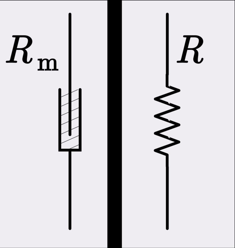
Resistance
The mechanical analogy of electrical resistance is the loss of energy of a moving system through such processes as friction. A mechanical component analogous to a resistor is a shock absorber and the property analogous to resistance is damping. A resistor is governed by the constitutive equation of Ohm's law,
The analogous equation in the mechanical domain is,
Electrical resistance represents the real part of electrical impedance. Likewise, mechanical resistance is the real part of mechanical impedance.
Inductance
The mechanical analogy of inductance in the impedance analogy is mass. A mechanical component analogous to an inductor is a large, rigid weight. An inductor is governed by the constitutive equation,
The analogous equation in the mechanical domain is Newton's second law of motion,
The impedance of an inductor is purely imaginary and is given by,
The analogous mechanical impedance is given by,
Capacitance
The mechanical analogy of capacitance in the impedance analogy is compliance. It is more common in mechanics to discuss stiffness, the inverse of compliance. The analogy of stiffness in the electrical domain is the less commonly used elastance, the inverse of capacitance. A mechanical component analogous to a capacitor is a spring. A capacitor is governed by the constitutive equation,
The analogous equation in the mechanical domain is a form of Hooke's law,
The impedance of a capacitor is purely imaginary and is given by,
The analogous mechanical impedance is given by,
Alternatively, one can write,
which is more directly analogous to the electrical expression when capacitance is used.
Resonator
A mechanical resonator consists of both a mass element and a compliance element. Mechanical resonators are analogous to electrical LC circuits consisting of inductance and capacitance. Real mechanical components unavoidably have both mass and compliance so it is a practical proposition to make resonators as a single component. In fact, it is more difficult to make a pure mass or pure compliance as a single component. A spring can be made with a certain compliance and mass minimised, or a mass can be made with compliance minimised, but neither can be eliminated altogether. Mechanical resonators are a key component of mechanical filters.
Generators
Analogues exist for the active electrical elements of the voltage source and the current source (generators). The mechanical analogue in the impedance analogy of the constant voltage generator is the constant force generator. The mechanical analogue of the constant current generator is the constant velocity generator.
An example of a constant force generator is the constant-force spring. This is analogous to a real voltage source, such as a battery, which remains near constant-voltage with load provided that the load resistance is much higher than the battery internal resistance. An example of a practical constant velocity generator is a lightly loaded powerful machine, such as a motor, driving a belt.
Transducers
Electromechanical systems require transducers to convert between the electrical and mechanical domains. They are analogous to two-port networks and like those can be described by a pair of simultaneous equations and four arbitrary parameters. There are numerous possible representations, but the form most applicable to the impedance analogy has the arbitrary parameters in units of impedance. In matrix form (with the electrical side taken as port 1) this representation is,
The element
Transformers
The mechanical analogy of a transformer is a simple machine such as a pulley or a lever. The force applied to the load can be greater or less than the input force depending on whether the mechanical advantage of the machine is greater or less than unity respectively. Mechanical advantage is analogous to transformer turns ratio in the impedance analogy. A mechanical advantage greater than unity is analogous to a step-up transformer and less than unity is analogous to a step-down transformer.
Simple resonant circuit
The figure shows a mechanical arrangement of a platform of mass M that is suspended above the substrate by a spring of stiffness S and a damper of resistance R. The impedance analogy equivalent circuit is shown to the right of this arrangement and consists of a series resonant circuit. This system has a resonant frequency, and may have a natural frequency of oscillation if not too heavily damped.
Model of the human ear
The circuit diagram shows an impedance analogy model of the human ear. The ear canal section is followed by a transformer representing the eardrum. The eardrum is the transducer between the acoustic waves in air in the ear canal and the mechanical vibrations in the bones of the middle ear. At the cochlea there is another change of medium from mechanical vibrations to the fluid filling the cochlea. This example thus demonstrates the power of electrical analogies in bringing together three domains (acoustic, mechanical and fluid flow) into a single unified whole. If the nerve impulses flowing to the brain had also been included in the model then the electrical domain would have made four domains encompassed in the model.
The cochlea portion of the circuit uses a finite element analysis of the continuous transmission line of the cochlear duct. An ideal representation of such a structure would use infinitesimal elements, and there would thus be an infinite number of them. In this model the cochlea is divided into 350 sections and each section is modelled using a small number of lumped elements.
Advantages and disadvantages
The principal advantage of the impedance analogy over its alternative, the mobility analogy, is that it maintains the analogy between electrical and mechanical impedance. That is, a mechanical impedance is represented as an electrical impedance and a mechanical resistance is represented as an electrical resistance in the electrical equivalent circuit. It is also natural to think of force as analogous to voltage (generator voltages are often called electromotive force) and velocity as analogous to current. It is this basic analogy that leads to the analogy between electrical and mechanical impedance.
The principal disadvantage of the impedance analogy is that it does not preserve the topology of the mechanical system. Elements that are in series in the mechanical system are in parallel in the electrical equivalent circuit and vice versa.
The impedance matrix representation of a transducer transforms force in the mechanical domain into current in the electrical domain. Likewise, velocity in the mechanical domain is transformed into voltage in the electrical domain. A two-port device that transforms a voltage into an analogous quantity can be represented as a simple transformer. A device that transforms a voltage into an analogue of the dual property of voltage (that is, current, whose analogue is velocity) is represented as a gyrator. Since force is analogous to voltage, not current, this may seem like a disadvantage on the face of it. However, many practical transducers, especially at audio frequencies, work by electromagnetic induction and are governed by just such a relationship. For instance, the force on a current-carrying conductor is given by,
History
The impedance analogy is sometimes called the Maxwell analogy after James Clerk Maxwell (1831–1879) who used mechanical analogies to explain his ideas of electromagnetic fields. However, the term impedance was not coined until 1886 (by Oliver Heaviside), the idea of complex impedance was introduced by Arthur E. Kennelly in 1893, and the concept of impedance was not extended into the mechanical domain until 1920 by Kennelly and Arthur Gordon Webster.
Henri Poincaré in 1907 was the first to describe a transducer as a pair of linear algebraic equations relating electrical variables (voltage and current) to mechanical variables (force and velocity). Wegel, in 1921, was the first to express these equations in terms of mechanical impedance as well as electrical impedance.