
 | ||
A frequency comb is a spectrum consisting of a series of discrete, equally spaced elements. Frequency combs can be generated by a number of mechanisms, including amplitude modulation (AM) of a continuous wave laser or stabilization of the pulse train generated by a mode locked laser. Much work has been devoted to the latter mechanism, which was developed around the turn of the twenty-first century and ultimately led to one half of the Nobel Prize in Physics being shared by John L. Hall and Theodor W. Hänsch in 2005.
Contents
- Using a mode locked laser
- Using four wave mixing
- Low frequency combs using electronics
- Frequency comb widening to one octave
- Carrierenvelope offset measurement
- Carrierenvelope offset control
- Applications
- History
- References
The frequency domain representation of a perfect frequency comb is a series of delta functions spaced according to
where
Combs spanning an octave in frequency (i.e., a factor of two) can be used to directly measure (and correct for drifts in)
Using a mode-locked laser
The most popular and famous way of generating a frequency comb is with a mode-locked laser. Such lasers produce a series of optical pulses separated in time by the round-trip time of the laser cavity. The spectrum of such a pulse train approximates a series of Dirac delta functions separated by the repetition rate (the inverse of the round trip time) of the laser. This series of sharp spectral lines is called a frequency comb or a frequency Dirac comb.
The most common lasers used for frequency comb generation are Ti:sapphire solid-state lasers or Er:fiber lasers with repetition rates typically between 100 MHz and 1 GHz or even going as high as 10 GHz.
Using four-wave mixing
Four-wave mixing is a process where intense light at three frequencies
Starting with intense light at two or more equally spaced frequencies, this process can generate light at more and more different equally spaced frequencies. For example, if there are a lot of photons at two frequencies
Therefore, a conceptually simple way to make an optical frequency comb is to take two high-power lasers of slightly different frequency, and shine them simultaneously through a photonic crystal fiber. This creates a frequency comb by four-wave mixing as described above.
An alternative method is to shine light into a microresonator (e.g. a microscopic glass circle that has whispering-gallery modes). This kind of structure naturally has a series of resonant modes with approximately-equally-spaced frequencies (similar to a Fabry–Pérot interferometer). Unfortunately the resonant modes are not exactly equally spaced due to dispersion. Nevertheless, the four-wave mixing effect above can create and stabilize a perfect frequency comb in such a structure. Basically, the system generates a perfect comb that overlaps the resonant modes as much as possible. In fact, nonlinear optics effects can shift the resonant modes to improve the overlap with the perfect comb even more. (The resonant mode frequencies depend on refractive index, which is altered by the optical Kerr effect.)
In the time domain, the light coming out of these structures does not necessarily look like a series of pulses, as the mode-locked laser does. Nevertheless, it is a stable frequency comb.
Low-frequency combs using electronics
A purely electronic device which generates a series of pulses, also generates a frequency comb. These are produced for electronic sampling oscilloscopes, but also used for frequency comparison of microwaves, because they reach up to 1 THz. Since they include 0 Hz they do not need the tricks which make up the rest of this article.
Frequency comb widening to one octave
To be usable, the comb must be widened to at least an octave: that is, the highest-frequency must be at least double the lowest frequency. One of three techniques may be used:
These processes generate new frequencies on the same comb for similar reasons as discussed above.
Carrier–envelope offset measurement
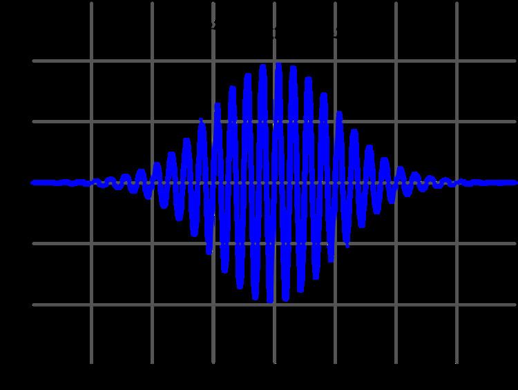
An increasing offset between the optical phase and the maximum of the wave envelope of an optical pulse can be seen on the right. Each line is displaced from a harmonic of the repetition rate by the carrier–envelope offset frequency. The carrier–envelope offset frequency is the rate at which the peak of the carrier frequency slips from the peak of the pulse envelope on a pulse-to-pulse basis.
Measurement of the carrier–envelope offset frequency is usually done with a self-referencing technique, in which the phase of one part of the spectrum is compared to its harmonic. Different possible approaches for carrier–envelope offset phase control were proposed in 1999. The two simplest approaches which require only one nonlinear optical process are described in the following.
In the 'frequency − 2 × frequency' technique, light at the lower energy side of the broadened spectrum is doubled using second harmonic generation (SHG) in a nonlinear crystal and a heterodyne beat is generated between that and light at the same wavelength on the upper energy side of the spectrum. This beat signal, detectable with a photodiode, includes a difference frequency component, which is the carrier–envelope offset frequency.
Alternatively difference frequency generation (DFG) can be used. From light of opposite ends of the broadened spectrum the difference frequency is generated in a nonlinear crystal and a heterodyne beat between this mixing product and light at the same wavelength of the original spectrum is measured. This beat frequency, detectable with a photodiode, is the carrier–envelope offset frequency.
Because the phase is measured directly and not the frequency, it is possible to set the frequency to zero and additionally lock the phase, but because the intensity of the laser and this detector is not very stable, and because the whole spectrum beats in phase source, one has to lock the phase on a fraction of the repetition rate.
Carrier–envelope offset control
In the absence of active stabilization, the repetition rate and carrier–envelope offset frequency would be free to drift. They vary with changes in the cavity length, refractive index of laser optics, and nonlinear effects such as the Kerr effect. The repetition rate can be stabilized using a piezoelectric transducer, which moves a mirror to change the cavity length.
In Ti:sapphire lasers using prisms for dispersion control, the carrier–envelope offset frequency can be controlled by tilting the high reflector mirror at the end of the prism pair. This can be done using piezoelectric transducers.
In high repetition rate Ti:sapphire ring lasers, which often use double-chirped mirrors to control dispersion, modulation of the pump power using an acousto-optic modulator is often used to control the offset frequency. The phase slip depends strongly on the Kerr effect, and by changing the pump power one changes the peak intensity of the laser pulse and thus the size of the Kerr phase shift. This shift is far smaller than 6 rad, so an additional device for coarse adjustment is needed. A pair of wedges, one moving in or out of the intra-cavity laser beam can be used for this purpose.
The breakthrough which led to a practical frequency comb was the development of technology for stabilizing the carrier–envelope offset frequency.
An alternative to stabilizing the carrier–envelope offset frequency is to cancel it completely by use of difference frequency generation (DFG). If the difference frequency of light of opposite ends of a broadened spectrum is generated in a nonlinear crystal, the resulting frequency comb is carrier–envelope offset-free since the two spectral parts contributing to the DFG share the same carrier–envelope offset frequency. This was first proposed in 1999 and recently demonstrated using an erbium fiber frequency comb at the telecom wavelength. This simple approach has the advantage that no electronic feedback loop is needed as in conventional stabilization techniques. It promises to be more robust and stable against environmental perturbations.
Applications
A frequency comb allows a direct link from radio frequency standards to optical frequencies. Current frequency standards such as atomic clocks operate in the microwave region of the spectrum, and the frequency comb brings the accuracy of such clocks into the optical part of the electromagnetic spectrum. A simple electronic feedback loop can lock the repetition rate to a frequency standard.
There are two distinct applications of this technique. One is the optical clock where an optical frequency is overlapped with a single tooth of the comb on a photodiode and a radio frequency is compared to the beat signal, the repetition rate, and the CEO-frequency. Applications for the frequency comb technique include optical metrology, frequency chain generation, optical atomic clocks, high precision spectroscopy, and more precise GPS technology.
The other is doing experiments with few cycle pulses, like above threshold ionization, attosecond pulses, highly efficient nonlinear optics or high harmonics generation. This can be single pulses so that no comb exists and therefore it is not possible to define a carrier envelope offset frequency, rather the carrier envelope offset phase is important. A second photodiode can be added to the setup to gather phase and amplitude in a single shot, or difference frequency generation can be used to even lock the offset on a single shot basis albeit with low power efficiency.
Without an actual comb one can look at the phase vs frequency. Without a carrier envelope offset all frequencies are cosines. That means all frequencies have the phase zero. The time origin is arbitrary. If a pulse comes at later times, the phase increases linearly with frequency, but still the zero frequency phase is zero. This phase at zero frequency is the carrier envelope offset. The second harmonic not only has twice the frequency but also twice the phase. That means for a pulse with zero offset the second harmonic of the low frequency tail is in phase with the fundamental of the high frequency tail and otherwise it is not. Spectral phase interferometry for direct electric-field reconstruction (SPIDER) measures how the phase increases with frequency, but it cannot determine the offset, so the name “electric field reconstruction” is a bit misleading.
In recent years, the frequency comb has been garnering interest for astro-comb applications, extending the use of the technique as a spectrographic observational tool in astronomy.
History
Theodor W. Hänsch and John L. Hall shared half of the 2005 Nobel Prize in Physics for contributions to the development of laser-based precision spectroscopy, including the optical frequency comb technique. The other half of the prize was awarded to Roy Glauber.
Also in 2005, the femtosecond comb technique was extended to the extreme ultraviolet range, enabling frequency metrology in that region of the spectrum.