
 | ||
In physics, the electric displacement field, denoted by D, is a vector field that appears in Maxwell's equations. It accounts for the effects of free and bound charge within materials while its sources are the free charges only. "D" stands for "displacement", as in the related concept of displacement current in dielectrics. In free space, the electric displacement field is equivalent to flux density, a concept that lends understanding to Gauss's law. In SI, it is expressed in units of coulomb per metre squared (C⋅m−2).
Contents
Definition
In a dielectric material the presence of an electric field E causes the bound charges in the material (atomic nuclei and their electrons) to slightly separate, inducing a local electric dipole moment. The electric displacement field D is defined as
where
The displacement field satisfies Gauss's law in a dielectric:
Electrostatic forces on ions or electrons in the material are governed by the electric field E in the material via the Lorentz Force. Also, D is not determined exclusively by the free charge. As E has a curl of zero in electrostatic situations, it follows that
The effect of this equation can be seen in the case of an object with a "frozen in" polarization like a bar electret, the electric analogue to a bar magnet. There is no free charge in such a material, but the inherent polarization gives rise to an electric field, demonstrating that the D field is not determined entirely by the free charge. The electric field is determined by using the above relation along with other boundary conditions on the polarization density to yield the bound charges, which will, in turn, yield the electric field.
In a linear, homogeneous, isotropic dielectric with instantaneous response to changes in the electric field, P depends linearly on the electric field,
where the constant of proportionality
where ε = ε0 εr is the permittivity, and εr = 1 + χ the relative permittivity of the material.
In linear, homogeneous, isotropic media, ε is a constant. However, in linear anisotropic media it is a tensor, and in nonhomogeneous media it is a function of position inside the medium. It may also depend upon the electric field (nonlinear materials) and have a time dependent response. Explicit time dependence can arise if the materials are physically moving or changing in time (e.g. reflections off a moving interface give rise to Doppler shifts). A different form of time dependence can arise in a time-invariant medium, as there can be a time delay between the imposition of the electric field and the resulting polarization of the material. In this case, P is a convolution of the impulse response susceptibility χ and the electric field E. Such a convolution takes on a simpler form in the frequency domain: by Fourier transforming the relationship and applying the convolution theorem, one obtains the following relation for a linear time-invariant medium:
where
At a boundary,
History
Gauss's law was formulated by Carl Friedrich Gauss in 1835, but was not published until 1867, meaning that the formulation and use of D were not earlier than 1835, and probably not earlier than the 1860s.
The earliest known use of the term is from the year 1864, in James Clerk Maxwell's paper A Dynamical Theory of the Electromagnetic Field. Maxwell used calculus to exhibit Michael Faraday's theory, that light is an electromagnetic phenomenon. Maxwell introduced the term D, specific capacity of electric induction, in a form different from the modern and familiar notations.
It was Oliver Heaviside who reformulated the complicated Maxwell's equations to the modern form. It wasn't until 1884 that Heaviside, concurrently with Willard Gibbs and Heinrich Hertz, grouped the equations together into a distinct set. This group of four equations was known variously as the Hertz–Heaviside equations and the Maxwell–Hertz equations, and is sometimes still known as the Maxwell–Heaviside equations; hence, it was probably Heaviside who lent D the present significance it now has.
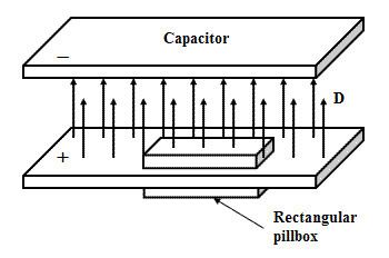
Example: Displacement field in a capacitor
Consider an infinite parallel plate capacitor placed in space (or in a medium) with no free charges present except on the capacitor. In SI units, the charge density on the plates is equal to the value of the D field between the plates. This follows directly from Gauss's law, by integrating over a small rectangular box straddling one plate of the capacitor:
On the sides of the box, dA is perpendicular to the field, so the integral over this section is zero. For the space inside the capacitor where the fields of the two plates add,
where A is surface area of the top face of the box and Qfree / A is the free surface charge density on the positive plate. Outside the capacitor, the fields of the two plates cancel each other and | E | = | D | = 0. If the space between the capacitor plates is filled with a linear homogeneous isotropic dielectric with permittivity ε, and the charge Qfree is kept constant, the total electric field E between the plates will be smaller than D by a factor of ε: | E | = Qfree / (εA). Alternatively, if the voltage and E are kept constant, the stored charges will increase by a factor of ε.
If the distance d between the plates of a finite parallel plate capacitor is much smaller than its lateral dimensions we can approximate it using the infinite case and obtain its capacitance as
where V is the potential difference sustained between the two plates. The partial cancellation of fields in the dielectric allows a larger amount of free charge to dwell on the two plates of the capacitor per unit potential drop than would be possible if the plates were separated by vacuum.