
 | ||
In electrical engineering, earth potential rise (EPR) also called ground potential rise (GPR) occurs when a large current flows to earth through an earth grid impedance. The potential relative to a distant point on the Earth is highest at the point where current enters the ground, and declines with distance from the source. Ground potential rise is a concern in the design of electrical substations because the high potential may be a hazard to people or equipment.
Contents
- Causes
- Step touch and mesh Voltage
- Mitigation
- Calculations
- Standards and regulations
- High voltage protection of telecommunication circuits
- References
The change of voltage over distance (potential gradient) may be so high that a person could be injured due to the voltage developed between two feet, or between the ground on which the person is standing and a metal object. Any conducting object connected to the substation earth ground, such as telephone wires, rails, fences, or metallic piping, may also be energized at the ground potential in the substation. This transferred potential is a hazard to people and equipment outside the substation.
Causes
Earth Potential Rise (EPR) is caused by electrical faults that occur at electrical substations, power plants, or high-voltage transmission lines. Short-circuit current flows through the plant structure and equipment and into the grounding electrode. The resistance of the Earth is non-zero, so current injected into the earth at the grounding electrode produces a potential rise with respect to a distant reference point. The resulting potential rise can cause hazardous voltage, many hundreds of metres away from the actual fault location. Many factors determine the level of hazard, including: available fault current, soil type, soil moisture, temperature, underlying rock layers, and clearing time to interrupt a fault.
Earth potential rise is a safety issue in the coordination of power and telecommunications services. An EPR event at a site such as an electrical distribution substation may expose personnel, users or structures to hazardous voltages.
Step, touch, and mesh Voltage
"Step voltage" is the voltage between the feet of a person standing near an energized grounded object. It is equal to the difference in voltage, given by the voltage distribution curve, between two points at different distances from the "electrode". A person could be at risk of injury during a fault simply by standing near the grounding point.
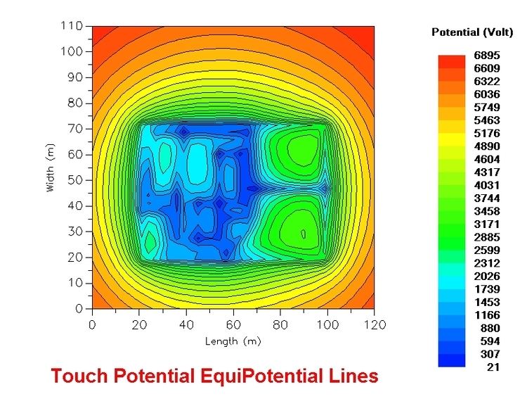
"Touch voltage" is the voltage between the energized object and the feet of a person in contact with the object. It is equal to the difference in voltage between the object and a point some distance away. The touch potential could be nearly the full voltage across the grounded object if that object is grounded at a point remote from the place where the person is in contact with it. For example, a crane that was grounded to the system neutral and that contacted an energized line would expose any person in contact with the crane or its uninsulated load line to a touch potential nearly equal to the full fault voltage.
To reduce the step and touch voltage we use the pebbles under the transformer.
Mitigation
An engineering analysis of the power system under fault conditions can be used to determine whether or not hazardous step and touch voltages will develop. The result of this analysis can show the need for protective measures and can guide the selection of appropriate precautions.
Several methods may be used to protect employees from hazardous ground-potential gradients, including equipotential zones, insulating equipment, and restricted work areas.
The creation of an equipotential zone will protect a worker standing within it from hazardous step and touch potentials. Such a zone can be produced through the use of a metal mat connected to the grounded object. Usually this metal mat (or ground mesh) is connected to buried ground rods to increase contact with the earth and effectively reduce grid impedance. In some cases, a grounding grid can be used to equalize the voltage within the grid. Equipotential zones will not, however, protect employees who are either wholly or partially outside the protected area. Bonding conductive objects in the immediate work area can also be used to minimize the potential between the objects and between each object and ground. (Bonding an object outside the work area can increase the touch potential to that object in some cases, however.)
The use of insulating personal protective equipment, such as rubber gloves, can protect employees handling grounded equipment and conductors from hazardous touch potentials. The insulating equipment must be rated for the highest voltage that can be impressed on the grounded objects under fault conditions (rather than for the full system voltage).
Restricting employees from areas where hazardous step or touch voltages could arise can protect employees not directly involved in the operation being performed. Employees on the ground in the vicinity of transmission structures should be kept at a distance where step voltages would be insufficient to cause injury. Employees should not handle grounded conductors or equipment likely to become energized to hazardous voltages unless the employees are within an equipotential zone or are protected by insulating equipment.
In cases such as an electrical substation, it is common practice to cover the surface with a high-resistivity layer of crushed stone or asphalt. The surface layer provides a high resistance between feet and ground grid and is an effective method to reduce the step and touch potential hazard.
Calculations
In principle, the potential of the earth grid Vgrid can be calculated using Ohm's Law if the fault current (If) and resistance of the grid (Zgrid) are known.
While the fault current from a distribution or transmission system can usually be calculated or estimated with precision, calculation of the earth grid resistance is more complicated. Difficulties in calculation arise from the extended and irregular shape of practical ground grids, and the varying resistivity of soil at different depths.
At points outside the earth grid, the potential rise decreases. The simplest case of the potential at a distance is the analysis of a driven rod electrode in homogeneous earth. The voltage profile is given by the following equation.
where
This case is a simplified system; practical earthing systems are more complex than a single rod, and the soil will have varying resistivity. It can, however, reliably be said that the resistance of a ground grid is inversely proportional to the area it covers; this rule can be used to quickly assess the degree of difficulty for a particular site. Programs running on desktop personal computers can model ground resistance effects and produce detailed calculations of ground potential rise, using various techniques including the finite element method.
Standards and regulations
The US Occupational Safety and Health Administration (OSHA) has designated EPR as a "known hazard" and has issued regulations governing the elimination of this hazard in the work place.
Protection and isolation equipment is made to national and international standards described by IEEE, National Electrical Codes (UL/CSA),FCC, and Telcordia.
IEEE Std. 80-2000 is a standard that addresses the calculation and mitigation of Step & Touch Potentials to acceptable levels.
High-voltage protection of telecommunication circuits
To protect wired communication and control circuits in sub stations, protective devices must be applied. High voltage can damage equipment and present a danger to personnel. Isolation devices prevent high voltages and currents from propagating from the sub station towards the telephone company's central office. Circuits may be isolated by transformers or using non-conductive fiber optic coupling. Surge arresting devices such as carbon blocks or gas tube shunts to ground do not isolate the circuit but divert high voltage currents from the protected circuit. This type of protection will not fully protect against the hazards of high voltage faults and lightning strikes.
Telecommunication standards define a "zone of influence" around a substation, inside of which, equipment and circuits must be protected from the effect of ground potential rise. In North American practice, the zone of influence is considered to be bounded by the "300 volt point", which is the point along a telecommunications circuit at which the GPR reaches 300 volts with respect to distant earth. The 300 volt point defining a zone of influence around a sub station is dependent on the ground resistivity in ohms, the amount of fault current in amperes. It will define a boundary a certain distance from the ground grid of the sub station. Each sub station has its own zone of influence since the variables explained above are different for each location.
In the UK, the Zone of Influence was historically measured as anywhere within 100m of the boundary of the high voltage compound at a Hot Site. Since 2007, it is allowable to use the Energy Networks Association (ENA) Recommendation S34 ('A Guide for Assessing the Rise of Earth Potential at Substation Sites') to calculate Hot Zone. This is now defined as a contour line marking where the Rise Of Earth Potential (ROEP) exceeds 430V for normal reliability power lines or 650V for high reliability lines. The Zone extends in a radius from any bonded metalwork such as the site earth electrode system and boundary fence. This may effectively reduce the overall size of the Hot Zone. However, strip earth electrodes, and any non-effectively insulated metallic sheath/ armouring of power cables which extend out of this zone would continue to be considered as 'hot' for a distance of 100m from the boundary, for a width of two meters either side of the conductor. It is the responsibility of the owning Electrical Supply Industry (ESI) to calculate the Hot Zone. Openreach (a BT Group company tasked with installing and maintaining the majority of telephone services in the UK) maintains a Hot Site Register, updated every 12 months by voluntarily supplied information from the ESI companies in the UK. Any Openreach engineer working in such an area must be Hot Site trained.
In some circumstances (such as when a 'cold' site is upgraded to 'hot' status), the Zone of Influence may encompass residential or commercial property which is not within the property of the Electrical Supply Industry. In these cases the cost of protecting each telephone circuit may be prohibitively high, so a drainage electrode may be supplied to effectively bring the local Earth Potential back to safe levels.