
 | ||
Directional stability is stability of a moving body or vehicle about an axis which is perpendicular to its direction of motion. Stability of a vehicle concerns itself with the tendency of a vehicle to return to its original direction in relation to the oncoming medium (water, air, road surface, etc.) when disturbed (rotated) away from that original direction. If a vehicle is directionally stable, a restoring moment is produced which is in a direction opposite to the rotational disturbance. This "pushes" the vehicle (in rotation) so as to return it to the original orientation, thus tending to keep the vehicle oriented in the original direction.
Contents
- Example road vehicle
- Introduction
- Stability analysis
- Relative effect of front and rear tyres
- Steering forces
- Limitations of the analysis
- References
Directional stability is frequently called "weather vaning" because a directionally stable vehicle free to rotate about its center of mass is similar to a weather vane rotating about its (vertical) pivot.
With the exception of spacecraft, vehicles generally have a recognisable front and rear and are designed so that the front points more or less in the direction of motion. Without this stability, they may tumble end over end, spin or orient themselves at a high angle of attack, even broadside on to the direction of motion. At high angles of attack, drag forces may become excessive, the vehicle may be impossible to control, or may even experience structural failure. In general, land, sea, air and underwater vehicles are designed to have a natural tendency to point in the direction of motion.
Example: road vehicle
Arrows, darts, rockets, and airships have tail surfaces to achieve stability. A road vehicle does not have elements specifically designed to maintain stability, but relies primarily on the distribution of mass.
Introduction
These points are best illustrated with an example which is familiar to most readers - the humble motor car.
The first stage of studying the stability of a road vehicle is the derivation of a reasonable approximation to the equations of motion.
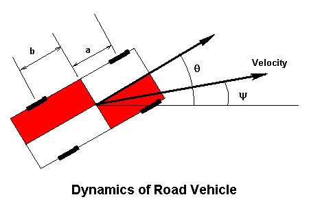
The diagram illustrates a four-wheel vehicle, in which the front axle is located a metres ahead of the centre of gravity and the rear axle is b metres aft of the cg. The body of the car is pointing in a direction
The net side force Y on the vehicle is the centripetal force causing the vehicle to change the direction it is traveling:
where M is the vehicle mass and V the speed. The angles are all assumed small, so the lateral force equation is:
The rotation of the body subjected to a yawing moment N is governed by:
where I is the moment of inertia in yaw. The forces and moments of interest arise from the distortion of the tyres. The angle between the direction the tread is rolling and the hub is called the slip angle. This is a bit of a misnomer, because the tyre as a whole does not actually slip, part of the region in contact with the road adheres, and part of the region slips. We assume that the tyre force is directly proportional to the slip angle (phi). This is made up of the slip of the vehicle as a whole modified by the angular velocity of the body. For the front axle:
whilst for the rear axle:
Let the constant of proportionality be k. The sideforce is, therefore:
The moment is:
Denoting the angular velocity
Let
Eliminating
This is called a second order linear homogeneous equation, and its properties form the basis of much of control theory.
Stability analysis
We do not need to solve the equation of motion explicitly to decide whether the solution diverges indefinitely or converges to zero following an initial perturbation. The form of the solution depends on the signs of the coefficients.
The coefficient of
By the same analogy, the coefficient of
The form of the solution depends only on the signs of the damping and stiffness terms. The four possible solution types are presented in the figure.
The only satisfactory solution requires both stiffness and damping to be positive.
The damping term is:
The tyre slip coefficient k is positive, as are the mass, moment of inertia and speed, so the damping is positive, and the directional motion should be dynamically stable.
The stiffness term is:
If the centre of gravity is ahead of the centre of the wheelbase (
Above this speed, the vehicle will be directionally unstable.
Relative effect of front and rear tyres
If for some reason (incorrect inflation pressure, worn tread) the tyres on one axle are incapable of generating significant lateral force, the stability will obviously be affected. Assume to begin with that the rear tyres are faulty, what is the effect on stability?
If the rear tyres produce no significant forces, the side force and yawing moment become:
The equation of motion becomes:
The coefficient of
The equation of motion becomes:
The coefficient of
It follows that the condition of the rear tyres is more critical to directional stability than the state of the front tyres. Also, locking the rear wheels by applying the handbrake, renders the vehicle directionally unstable, causing it to spin. Since the vehicle is not under control during the spin, the 'handbrake turn' is usually illegal on public roads.
Steering forces
Deflecting the steering changes the slip angle of the front tyres, generating a sideforce. With conventional steering, the tyres are deflected by different amounts, but for the purposes of this analysis, the additional slip will be considered equal for both front tyres.
The side force becomes:
where
Including the steering term introduces a forced response:
The steady state response is with all time derivatives set to zero. Stability requires that the coefficient of
This is a function of speed. When the speed is low, the slip is negative and the body points out of the corner (it understeers). At a speed given by:
The body points in the direction of motion. Above this speed, the body points into the corner (oversteers).
As an example:
Evidently moving the centre of gravity forwards increases this speed, giving the vehicle a tendency to understeer.
Note: Installing a heavy, powerful engine in a light weight production vehicle designed around a small engine increases both its directional stability, and its tendency to understeer. The result is an overpowered vehicle with poor cornering performance.
Even worse is the installation of an oversized power unit into a rear engined production vehicle without corresponding modification of suspension or mass distribution, as the result will be directionally unstable at high speed.
Limitations of the analysis
The forces arising from slip depend on the loading on the tyre as well as the slip angle, this effect has been ignored, but could be taken into account by assuming different values of k for the front and rear axles. Roll motion due to cornering will redistribute the tyre loads between the nearside and offside of the vehicle, again modifying the tyre forces. Engine torque likewise re-distributes the load between front and rear tyres.
A full analysis should also take account of the suspension response.
The complete analysis is essential for the design of high performance road vehicles, but is beyond the scope of this article.