
 | ||
In fluid dynamics, the drag coefficient (commonly denoted as:
Contents
The drag coefficient of any object comprises the effects of the two basic contributors to fluid dynamic drag: skin friction and form drag. The drag coefficient of a lifting airfoil or hydrofoil also includes the effects of lift-induced drag. The drag coefficient of a complete structure such as an aircraft also includes the effects of interference drag.
Definition
The drag coefficient
where:
The reference area depends on what type of drag coefficient is being measured. For automobiles and many other objects, the reference area is the projected frontal area of the vehicle. This may not necessarily be the cross sectional area of the vehicle, depending on where the cross section is taken. For example, for a sphere
For airfoils, the reference area is the nominal wing area. Since this tends to be large compared to the frontal area, the resulting drag coefficients tend to be low, much lower than for a car with the same drag, frontal area, and speed.
Airships and some bodies of revolution use the volumetric drag coefficient, in which the reference area is the square of the cube root of the airship volume (volume to the two-thirds power). Submerged streamlined bodies use the wetted surface area.
Two objects having the same reference area moving at the same speed through a fluid will experience a drag force proportional to their respective drag coefficients. Coefficients for unstreamlined objects can be 1 or more, for streamlined objects much less.
Background
The drag equation
is essentially a statement that the drag force on any object is proportional to the density of the fluid and proportional to the square of the relative flow speed between the object and the fluid.
Cd is not a constant but varies as a function of flow speed, flow direction, object position, object size, fluid density and fluid viscosity. Speed, kinematic viscosity and a characteristic length scale of the object are incorporated into a dimensionless quantity called the Reynolds number
For certain body shapes, the drag coefficient
For a streamlined body to achieve a low drag coefficient, the boundary layer around the body must remain attached to the surface of the body for as long as possible, causing the wake to be narrow. A high form drag results in a broad wake. The boundary layer will transition from laminar to turbulent if Reynolds number of the flow around the body is sufficiently great. Larger velocities, larger objects, and lower viscosities contribute to larger Reynolds numbers.
For other objects, such as small particles, one can no longer consider that the drag coefficient
A
General
In general,
Aircraft
As noted above, aircraft use their wing area as the reference area when computing
Concept
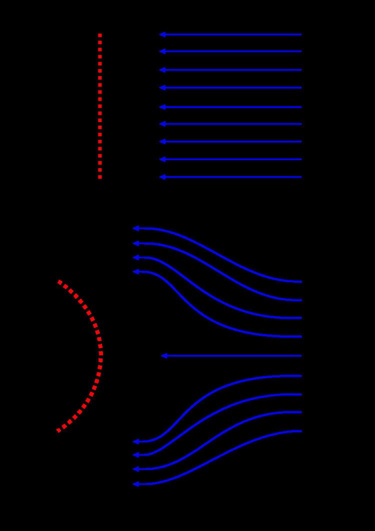
Drag, in the context of fluid dynamics, refers to forces that act on a solid object in the direction of the relative flow velocity (note that the diagram below shows the drag in the opposite direction to the flow). The aerodynamic forces on a body come primarily from differences in pressure and viscous shearing stresses. Thereby, the drag force on a body could be divided into two components, namely frictional drag (viscous drag) and pressure drag (form drag). The net drag force could be decomposed as follows:
where:
Therefore, when the drag is dominated by a frictional component, the body is called a streamlined body; whereas in the case of dominant pressure drag, the body is called a blunt body. Thus, the shape of the body and the angle of attack determine the type of drag. For example, an airfoil is considered as a body with a small angle of attack by the fluid flowing across it. This means that it has attached boundary layers, which produce much less pressure drag.
The wake produced is very small and drag is dominated by the friction component. Therefore, such a body (here an airfoil) is described as streamlined, whereas for bodies with fluid flow at high angles of attack, boundary layer separation takes place. This mainly occurs due to adverse pressure gradients at the top and rear parts of an airfoil.
Due to this, wake formation takes place, which consequently leads to eddy formation and pressure loss due to pressure drag. In such situations, the airfoil is stalled and has higher pressure drag than friction drag. In this case, the body is described as a blunt body.
A streamlined body looks like a fish (Tuna, Oropesa, etc.) or an airfoil with small angle of attack, whereas a blunt body looks like a brick, a cylinder or an airfoil with high angle of attack. For a given frontal area and velocity, a streamlined body will have lower resistance than a blunt body. Cylinders and spheres are taken as blunt bodies because the drag is dominated by the pressure component in the wake region at high Reynolds number.
To reduce this drag, either the flow separation could be reduced or the surface area in contact with the fluid could be reduced (to reduce friction drag). This reduction is necessary in devices like cars, bicycle, etc. to avoid vibration and noise production.
Practical example
The aerodynamic design of cars has evolved from the 1920s to the end of the 20th century. This change in design from a blunt body to a more streamlined body reduced the drag coefficient from about 0.95 to 0.30.