
 | ||
The cavity magnetron is a high-powered vacuum tube that generates microwaves using the interaction of a stream of electrons with a magnetic field while moving past a series of open metal cavities (cavity resonators). Electrons pass by the openings to these cavities and cause radio waves to oscillate within, similar to the way a guitar resonates sound from its sound box via the oscillation of its strings. The frequency of the microwaves produced, the resonant frequency, is determined by the cavities' physical dimensions. Unlike other vacuum tubes such as a klystron or a traveling-wave tube (TWT), the magnetron cannot function as an amplifier in order to increase the intensity of an applied microwave signal; the magnetron serves solely as an oscillator, generating a microwave signal from direct current electricity supplied to the vacuum tube.
Contents
- Conventional tube design
- Hull or single anode magnetron
- Split anode magnetron
- Cavity magnetron
- Common features
- Radar
- Heating
- Lighting
- History
- Health hazards
- References
An early form of magnetron was invented by H. Gerdien in 1910. Another form of magnetron tube, the split-anode magnetron, was invented by Albert Hull in 1920, but it wasn't capable of high frequencies and was of little use. Similar devices were experimented with by many teams through the 1920s and 1930s. On November 27, 1935, Hans Erich Hollmann applied for a patent for the first multiple-cavity magnetron, which he received on July 12, 1938, but the more stable klystron was preferred for most German radars during World War II. The cavity magnetron tube was later improved by John Randall and Harry Boot in 1940 at the University of Birmingham, England. The high power of pulses from their device made centimeter-band radar practical for the Allies of World War II, with shorter wavelength radars allowing detection of smaller objects from smaller antennas. The compact cavity magnetron tube drastically reduced the size of radar sets so that they could be more easily installed in night-fighter aircraft, anti-submarine aircraft and escort ships.
In the post-war era the magnetron became less widely used in the radar role. This was because the magnetron's output changes from pulse to pulse, both in frequency and phase. This makes the signal unsuitable for pulse-to-pulse comparisons, which is widely used for detecting and removing "clutter" from the radar display. The magnetron remains in use in some radars, but has become much more common as a low-cost microwave source for microwave ovens. In this form, approximately one billion magnetrons are in use today.
Conventional tube design
In a conventional electron tube (vacuum tube), electrons are emitted from a negatively charged, heated component called the cathode and are attracted to a positively charged component called the anode. The components are normally arranged concentrically, placed within a tubular-shaped container from which all air has been evacuated, so that the electrons can move freely (hence the name "vacuum" tubes, called "valves" by the British)
If a third electrode is inserted between the cathode and the anode (called a control grid), the flow of electrons between the cathode and anode can be regulated by varying the electric charge on this third electrode. This allows the resulting electron tube (called a "triode" because it now has three electrodes) to function as an amplifier because small variations in the electric charge applied to the control grid will result in identical variations in the much larger current of electrons flowing between the cathode and anode.
Hull or single-anode magnetron
The idea of using a grid for control was patented by Lee de Forest, resulting in considerable research into alternate tube designs that would avoid his patents. One concept used a magnetic field instead of an electrical charge to control current flow, leading to the development of the magnetron tube. In this design, the tube was made with two electrodes, typically with the cathode in the form of a metal rod in the center, and the anode as a cylinder around it. The tube was placed between the poles of a horseshoe magnet arranged such that the magnetic field was aligned parallel to the axis of the electrodes.
With no magnetic field present, the tube operates as a diode, with electrons flowing directly from the cathode to the anode. In the presence of the magnetic field, the electrons will experience a force at right angles to their direction of motion, according to the left-hand rule. In this case, the electrons follow a curved path between the cathode and anode. The curvature of the path can be controlled by varying either the magnetic field, using an electromagnet, or by changing the electrical potential between the electrodes.
At very high magnetic field settings the electrons are forced back onto the cathode, preventing current flow. At the opposite extreme, with no field, the electrons are free to flow straight from the cathode to the anode. There is a point between the two extremes, the critical value or Hull cut-off magnetic field (and cut-off voltage), where the electrons just reach the anode. At fields around this point, the device operates similar to a triode. However, magnetic control, due to hysteresis and other effects, results in a slower and less faithful response to control current than electrostatic control using a control grid in a conventional triode (not to mention greater weight and complexity), so magnetrons saw limited use in conventional electronic designs.
It was noticed that when the magnetron was operating at the critical value, it would emit energy in the radio frequency spectrum. This occurs because a few of the electrons, instead of reaching the anode, continue to circle in the space between the cathode and the anode. Due to an effect now known as cyclotron radiation, these electrons radiate radio frequency energy. The effect is not very efficient. Eventually the electrons hit one of the electrodes, so the number in the circulating state at any given time is a small percentage of the overall current. It was also noticed that the frequency of the radiation depends on the size of the tube, and even early examples were built that produced signals in the microwave region.
Early conventional tube systems were limited to the high frequency bands, and although very high frequency systems became widely available in the late 1930s, the ultra high frequency and microwave regions were well beyond the ability of conventional circuits. The magnetron was one of the few devices able to generate signals in the microwave band and it was the only one that was able to produce high power at centimeter wavelengths.
Split-anode magnetron
The original magnetron was very difficult to keep operating at the critical value, and even then the number of electrons in the circling state at any time was fairly low. This meant that it produced very low-power signals. Nevertheless, as one of the few devices known to create microwaves, interest in the device and potential improvements was widespread.
The first major improvement was the split-anode magnetron, also known as a negative-resistance magnetron. As the name implies, this design used an anode that was split in two, creating two half-cylinders. When both were charged to the same voltage the system worked like the original model. But by altering the voltage of the two plates, the electron's trajectory could be modified so that they would naturally travel towards the lower voltage side. The plates were connected to an oscillator that reversed the relative voltage of the two plates at a given frequency.
At any given instant, the electron will naturally be pushed towards the lower-voltage side of the tube. The electron will then oscillate back and forth as the voltage changes. At the same time, a strong magnetic field is applied, stronger than the critical value in the original design. This would normally cause the electron to circle back to the cathode, but due to the oscillating electrical field, the electron instead follows a looping path that continues toward the anodes.
Since all of the electrons in the flow experienced this looping motion, the amount of RF energy being radiated was greatly improved. And as the motion occurred at any field level beyond the critical value, it was no longer necessary to carefully tune the fields and voltages, and the overall stability of the device was greatly improved. Unfortunately, the higher field also meant that electrons often circled back to the cathode, depositing their energy on it and causing it to heat up. As this normally causes more electrons to be released, it could sometimes lead to a runaway effect.
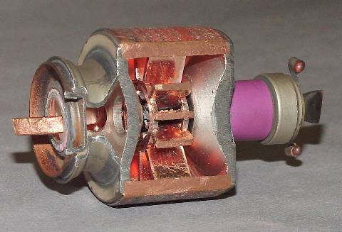
Cavity magnetron
The great advance in magnetron design was the cavity magnetron or electron-resonance magnetron, which works on entirely different principles. In this design the oscillation is created by the physical shaping of the anode, rather than external circuits or fields.
Mechanically, the cavity magnetron consists of a large cylinder of metal with a hole drilled through the center of the circular face. A wire acting as the cathode is run down the center of this hole, and the metal block itself forms the anode. Around this hole, known as the "interaction space", are a number of similar holes drilled parallel to the interaction space, separated only a very short distance away. A small slot is cut between the interaction space and each of these additional holes, the "resonators". The resulting block looks something like the cylinder on a revolver, with a somewhat larger central hole. (Early models were actually cut using Colt pistol jigs.) The parallel sides of the slots acted as a capacitor while the anode block itself provided an inductor analog. Thus, each cavity formed its own resonant circuit, the frequency of which was defined by the energy of the electrons and the physical dimensions of the cavity.
The magnetic field is set to a value well below the critical, so the electrons follow arcing paths towards the anode. When they strike the anode, they cause it to become negatively charged in that region. As this process is random, some areas will become more or less charged than the areas around them. The anode is constructed of a highly conductive material, almost always copper, so these differences in voltage cause currents to appear to even them out. Since the current has to flow around the outside of the cavity, this process takes time. During that time additional electrons will avoid the hot spots and be deposited further along the anode, as the additional current flowing around it arrives too. This causes an oscillating current to form as the current tries to equalize one spot, then another.
The oscillating currents flowing around the cavities, and their effect on the electron flow within the tube, causes large amounts of microwave radiofrequency energy to be generated in the cavities. The cavities are open on one end, so the entire mechanism forms a single larger microwave oscillator. A "tap", normally a wire formed into a loop, extracts microwave energy from one of the cavities. In some systems the tap wire is replaced by an open hole, which allows the microwaves to flow into a waveguide.
As the oscillation takes some time to set up, and is inherently random at the start, subsequent startups will have different output parameters. Phase is almost never preserved, which makes the magnetron difficult to use in phased array systems. Frequency also drifts pulse to pulse, a more difficult problem for a wider array of radar systems. Neither of these present a problem for continuous-wave radars, nor for microwave ovens.
Common features
All cavity magnetrons consist of a heated cathode placed at a high (continuous or pulsed) negative potential created by a high-voltage, direct-current power supply. The cathode is placed in the center of an evacuated, lobed, circular chamber. A magnetic field parallel to the filament is imposed by a permanent magnet. The magnetic field causes the electrons, attracted to the (relatively) positive outer part of the chamber, to spiral outward in a circular path, a consequence of the Lorentz force. Spaced around the rim of the chamber are cylindrical cavities. Slots are cut along the length of the cavities that open into the central, common cavity space. As electrons sweep past these slots, they induce a high-frequency radio field in each resonant cavity, which in turn causes the electrons to bunch into groups. (This principle of cavity resonator is very similar to blowing a stream of air across the open top of a glass pop bottle.) A portion of the radio frequency energy is extracted by a short antenna that is connected to a waveguide (a metal tube, usually of rectangular cross section). The waveguide directs the extracted RF energy to the load, which may be a cooking chamber in a microwave oven or a high-gain antenna in the case of radar.
The sizes of the cavities determine the resonant frequency, and thereby the frequency of the emitted microwaves. However, the frequency is not precisely controllable. The operating frequency varies with changes in load impedance, with changes in the supply current, and with the temperature of the tube. This is not a problem in uses such as heating, or in some forms of radar where the receiver can be synchronized with an imprecise magnetron frequency. Where precise frequencies are needed, other devices, such as the klystron are used.
The magnetron is a self-oscillating device requiring no external elements other than a power supply. A well-defined threshold anode voltage must be applied before oscillation will build up; this voltage is a function of the dimensions of the resonant cavity, and the applied magnetic field. In pulsed applications there is a delay of several cycles before the oscillator achieves full peak power, and the build-up of anode voltage must be coordinated with the build-up of oscillator output.
Where there are an even number of cavities, two concentric rings can connect alternate cavity walls to prevent inefficient modes of oscillation. This is called pi-strapping because the two straps lock the phase difference between adjacent cavities at pi radians (180°).
The modern magnetron is a fairly efficient device. In a microwave oven, for instance, a 1.1-kilowatt input will generally create about 700 watts of microwave power, an efficiency of around 65%. (The high-voltage and the properties of the cathode determine the power of a magnetron.) Large S band magnetrons can produce up to 2.5 megawatts peak power with an average power of 3.75 kW. Some large magnetrons are water cooled. The magnetron remains in widespread use in roles which require high power, but where precise control over frequency and phase is unimportant.
Radar
In a radar set, the magnetron's waveguide is connected to an antenna. The magnetron is operated with very short pulses of applied voltage, resulting in a short pulse of high power microwave energy being radiated. As in all primary radar systems, the radiation reflected off a target is analyzed to produce a radar map on a screen.
Several characteristics of the magnetron's output make radar use of the device somewhat problematic. The first of these factors is the magnetron's inherent instability in its transmitter frequency. This instability results not only in frequency shifts from one pulse to the next, but also a frequency shift within an individual transmitted pulse. The second factor is that the energy of the transmitted pulse is spread over a relatively wide frequency spectrum, which requires the receiver to have a correspondingly wide bandwidth. This wide bandwidth allows ambient electrical noise to be accepted into the receiver, thus obscuring somewhat the weak radar echoes, thereby reducing overall receiver signal-to-noise ratio and thus performance. The third factor, depending on application, is the radiation hazard caused by the use of high power electromagnetic radiation. In some applications, for example a marine radar mounted on a recreational vessel, a radar with a magnetron output of 2 to 4 kilowatts is often found mounted very near an area occupied by crew or passengers. In practical use these factors have been overcome, or merely accepted, and there are today thousands of magnetron aviation and marine radar units in service. Recent advances in aviation weather avoidance radar and in marine radar have successfully replaced the magnetron with semiconductor microwave oscillators, which have a narrower output frequency range. These allow a narrower receiver bandwidth to be used, and the higher signal to noise ratio in turn allows a lower transmitter power, reducing exposure to EMR.
Heating
In microwave ovens, the waveguide leads to a radio frequency-transparent port into the cooking chamber. As the fixed dimensions of the chamber, and its physical closeness to the magnetron, would normally create standing wave patterns in the chamber, a motorized fan-like stirrer is placed in the waveguide to randomize the pattern. This is not always effective for larger objects in the chamber, and most modern microwave ovens also include a rotating table for the food to sit on, the turntable.
Lighting
In microwave-excited lighting systems, such as a sulfur lamp, a magnetron provides the microwave field that is passed through a waveguide to the lighting cavity containing the light-emitting substance (e.g., sulfur, metal halides, etc.). Although efficient, these lamps are much more complex than other methods of lighting and therefore not commonly used.
History
In 1910 H. Gerdien invented a magnetron. In 1912, Swiss physicist Heinrich Greinacher was looking for new ways to calculate the electron mass. He settled on a system consisting of a diode with a cylindrical anode surrounding a rod-shaped cathode, placed in the middle of a magnet. The attempt to measure the electron mass failed because he was unable to achieve a good vacuum in the tube. However, as part of this work, Greinacher developed mathematical models of the motion of the electrons in the crossed magnetic and electric fields.
In the US, Albert Hull put this work to use in an attempt to bypass Western Electric's patents on the triode, which they had gained by buying Lee De Forest's patents on the control of current flow using electric fields via the "grid". Hull intended to use a variable magnetic field, instead of an electrostatic one, to control the flow of the electrons from the cathode to the anode. Working at General Electric's Research Laboratories in Schenectady, New York, Hull built tubes that provided switching through the control of the ratio of the magnetic and electric field strengths. He released several papers and patents on the concept in 1921.
Hull's magnetron was not originally intended to generate VHF (very-high-frequency) electromagnetic waves. However, in 1924, Czech physicist August Žáček (1886–1961) and German physicist Erich Habann (1892–1968) independently discovered that the magnetron could generate waves of 100 megahertz to 1 gigahertz. Žáček, a professor at Prague's Charles University, published first; however, he published in a journal with a small circulation and thus attracted little attention. Habann, a student at the University of Jena, investigated the magnetron for his doctoral dissertation of 1924. Throughout the 1920s, Hull and other researchers around the world worked to develop the magnetron. Most of these early magnetrons were glass vacuum tubes with multiple anodes. However, the two-pole magnetron, also known as a split-anode magnetron, had relatively low efficiency. The cavity version (properly referred to as a resonant-cavity magnetron) proved to be far more useful. In 1937–1940 a multi-cavity magnetron was built by the British physicist John Randall, together with a team of British coworkers, for the British and American military radar installations in World War II.
While radar was being developed during World War II, there arose an urgent need for a high-power microwave generator that worked at shorter wavelengths (around 10 cm (3 GHz)) rather than the 150 cm (200 MHz) that was available from tube-based generators of the time. It was known that a multi-cavity resonant magnetron had been developed and patented in 1935 by Hans Hollmann in Berlin. However, the German military considered the frequency drift of Hollman's device to be undesirable, and based their radar systems on the klystron instead. But klystrons could not at that time achieve the high power output that magnetrons eventually reached. This was one reason that German night fighter radars — which never strayed beyond the low-UHF band to start with for front-line nocturnal fighter aircraft — were not a match for their British counterparts.
In 1940, at the University of Birmingham in the United Kingdom, John Randall and Harry Boot produced a working prototype similar to Hollman's cavity magnetron, but added liquid cooling and a stronger cavity. Randall and Boot soon managed to increase its power output 100 fold. Instead of abandoning the magnetron due to its frequency instability, they sampled the output signal and synchronized their receiver to whatever frequency was actually being generated. In 1941, the problem of frequency instability was solved by coupling ("strapping") alternate cavities within the magnetron. (For an overview of early magnetron designs, including that of Boot and Randall, see )
Because France had just fallen to the Nazis and Britain had no money to develop the magnetron on a massive scale, Churchill agreed that Sir Henry Tizard should offer the magnetron to the Americans in exchange for their financial and industrial help (the Tizard Mission). An early 10 kW version, built in England by the General Electric Company Research Laboratories, Wembley, London (not to be confused with the similarly named American company General Electric), was given to the US government in September 1940. The British magnetron was a thousand times more powerful than the best American transmitter at the time and produced accurate pulses. At the time the most powerful equivalent microwave producer available in the US (a klystron) had a power of only ten watts. The cavity magnetron was widely used during World War II in microwave radar equipment and is often credited with giving Allied radar a considerable performance advantage over German and Japanese radars, thus directly influencing the outcome of the war. It was later described by the historian James Phinney Baxter III as "[t]he most valuable cargo ever brought to our shores".
The Bell Telephone Laboratories made a producible version from the magnetron delivered to America by the Tizard Mission, and before the end of 1940, the Radiation Laboratory had been set up on the campus of the Massachusetts Institute of Technology to develop various types of radar using the magnetron. By early 1941, portable centimetric airborne radars were being tested in American and British aircraft. In late 1941, the Telecommunications Research Establishment in Great Britain used the magnetron to develop a revolutionary airborne, ground-mapping radar codenamed H2S. The H2S radar was in part developed by Alan Blumlein and Bernard Lovell.
Centimetric radar, made possible by the cavity magnetron, allowed for the detection of much smaller objects and the use of much smaller antennas. The combination of small-cavity magnetrons, small antennas, and high resolution allowed small, high quality radars to be installed in aircraft. They could be used by maritime patrol aircraft to detect objects as small as a submarine periscope, which allowed aircraft to attack and destroy submerged submarines which had previously been undetectable from the air. Centimetric contour mapping radars like H2S improved the accuracy of Allied bombers used in the strategic bombing campaign, despite the existence of the German FuG 350 Naxos device to specifically detect it. Centimetric gun-laying radars were likewise far more accurate than the older technology. They made the big-gunned Allied battleships more deadly and, along with the newly developed proximity fuze, made anti-aircraft guns much more dangerous to attacking aircraft. The two coupled together and used by anti-aircraft batteries, placed along the flight path of German V-1 flying bombs on their way to London, are credited with destroying many of the flying bombs before they reached their target.
Since then, many millions of cavity magnetrons have been manufactured; while some have been for radar the vast majority have been for microwave ovens. The use in radar itself has dwindled to some extent, as more accurate signals have generally been needed and developers have moved to klystron and traveling-wave tube systems for these needs.
Health hazards
At least one hazard in particular is well known and documented. As the lens of the eye has no cooling blood flow, it is particularly prone to overheating when exposed to microwave radiation. This heating can in turn lead to a higher incidence of cataracts in later life. A microwave oven with a warped door or poor microwave sealing can be hazardous.
There is also a considerable electrical hazard around magnetrons, as they require a high voltage power supply.
Some magnetrons have beryllium oxide (beryllia) ceramic insulators, which are dangerous if crushed and inhaled, or otherwise ingested. Single or chronic exposure can lead to berylliosis, an incurable lung condition. In addition, beryllia is listed as a confirmed human carcinogen by the IARC; therefore, broken ceramic insulators or magnetrons should not be directly handled.
All magnetrons contain a small amount of thorium mixed with tungsten in their filament. While this is a radioactive metal, the risk of cancer is low as it never gets airborne in normal usage. Only if the filament is taken out of the magnetron, finely crushed, and inhaled can it pose a health hazard.