
Acronym CE | ||
 | ||
Analytes BiomoleculesChiral molecules Related Hyphenated Capillary electrophoresis mass spectrometry | ||
Capillary electrophoresis (CE) is a family of electrokinetic separation methods performed in submillimeter diameter capillaries and in micro- and nanofluidic channels. Very often, CE refers to capillary zone electrophoresis (CZE), but other electrophoretic techniques including capillary gel electrophoresis (CGE), capillary isoelectric focusing (CIEF), capillary isotachophoresis and micellar electrokinetic chromatography (MEKC) belong also to this class of methods. In CE methods, analytes migrate through electrolyte solutions under the influence of an electric field. Analytes can be separated according to ionic mobility and/or partitioning into an alternate phase via non-covalent interactions. Additionally, analytes may be concentrated or "focused" by means of gradients in conductivity and pH.
Contents
Instrumentation
The instrumentation needed to perform capillary electrophoresis is relatively simple. A basic schematic of a capillary electrophoresis system is shown in figure 1. The system's main components are a sample vial, source and destination vials, a capillary, electrodes, a high voltage power supply, a detector, and a data output and handling device. The source vial, destination vial and capillary are filled with an electrolyte such as an aqueous buffer solution. To introduce the sample, the capillary inlet is placed into a vial containing the sample. Sample is introduced into the capillary via capillary action, pressure, siphoning, or electrokinetically, and the capillary is then returned to the source vial. The migration of the analytes is initiated by an electric field that is applied between the source and destination vials and is supplied to the electrodes by the high-voltage power supply. In the most common mode of CE, all ions, positive or negative, are pulled through the capillary in the same direction by electroosmotic flow. The analytes separate as they migrate due to their electrophoretic mobility, and are detected near the outlet end of the capillary. The output of the detector is sent to a data output and handling device such as an integrator or computer. The data is then displayed as an electropherogram, which reports detector response as a function of time. Separated chemical compounds appear as peaks with different retention times in an electropherogram. Capillary electrophoresis was first combined with mass spectrometry by Richard D. Smith and coworkers, and provides extremely high sensitivity for the analysis of very small sample sizes. Despite the very small sample sizes (typically only a few nanoliters of liquid are introduced into the capillary), high sensitivity and sharp peaks are achieved in part due to injection strategies that result in concentration of analytes into a narrow zone near the inlet of the capillary. This is achieved in either pressure or electrokinetic injections simply by suspending the sample in a buffer of lower conductivity (e.g. lower salt concentration) than the running buffer. A process called field-amplified sample stacking (a form of isotachophoresis) results in concentration of analyte in a narrow zone at the boundary between the low-conductivity sample and the higher-conductivity running buffer.
To achieve greater sample throughput, instruments with arrays of capillaries are used to analyze many samples simultaneously. Such capillary array electrophoresis (CAE) instruments with 16 or 96 capillaries are used for medium- to high-throughput capillary DNA sequencing, and the inlet ends of the capillaries are arrayed spatially to accept samples directly from SBS-standard footprint 96-well plates. Certain aspects of the instrumentation (such as detection) are necessarily more complex than for a single-capillary system, but the fundamental principles of design and operation are similar to those shown in Figure 1.
Detection
Separation by capillary electrophoresis can be detected by several detection devices. The majority of commercial systems use UV or UV-Vis absorbance as their primary mode of detection. In these systems, a section of the capillary itself is used as the detection cell. The use of on-tube detection enables detection of separated analytes with no loss of resolution. In general, capillaries used in capillary electrophoresis are coated with a polymer (frequently polyimide or Teflon) for increased flexibility. The portion of the capillary used for UV detection, however, must be optically transparent. For polyimide-coated capillaries, a segment of the coating is typically burned or scraped off to provide a bare window several millimeters long. This bare section of capillary can break easily, and capillaries with transparent coatings are available to increase the stability of the cell window. The path length of the detection cell in capillary electrophoresis (~ 50 micrometers) is far less than that of a traditional UV cell (~ 1 cm). According to the Beer-Lambert law, the sensitivity of the detector is proportional to the path length of the cell. To improve the sensitivity, the path length can be increased, though this results in a loss of resolution. The capillary tube itself can be expanded at the detection point, creating a "bubble cell" with a longer path length or additional tubing can be added at the detection point as shown in figure 2. Both of these methods, however, will decrease the resolution of the separation. Post-column detection utilizing a sheath flow configuration has also been described.
Fluorescence detection can also be used in capillary electrophoresis for samples that naturally fluoresce or are chemically modified to contain fluorescent tags. This mode of detection offers high sensitivity and improved selectivity for these samples, but cannot be utilized for samples that do not fluoresce. Numerous labeling strategies are used to create fluorescent derivatives or conjugates of non-fluorescent molecules, including proteins and DNA. The set-up for fluorescence detection in a capillary electrophoresis system can be complicated. The method requires that the light beam be focused on the capillary, which can be difficult for many light sources. Laser-induced fluorescence has been used in CE systems with detection limits as low as 10−18 to 10−21 mol. The sensitivity of the technique is attributed to the high intensity of the incident light and the ability to accurately focus the light on the capillary. Multi-color fluorescence detection can be achieved by including multiple dichroic mirrors and bandpass filters to separate the fluorescence emission amongst multiple detectors (e.g., photomultiplier tubes), or by using a prism or grating to project spectrally resolved fluorescence emission onto a position-sensitive detector such as a CCD array. CE systems with 4- and 5-color LIF detection systems are used routinely for capillary DNA sequencing and genotyping ("DNA fingerprinting") applications.
In order to obtain the identity of sample components, capillary electrophoresis can be directly coupled with mass spectrometers or Surface Enhanced Raman Spectroscopy (SERS). In most systems, the capillary outlet is introduced into an ion source that utilizes electrospray ionization (ESI). The resulting ions are then analyzed by the mass spectrometer. This set-up requires volatile buffer solutions, which will affect the range of separation modes that can be employed and the degree of resolution that can be achieved. The measurement and analysis are mostly done with a specialized gel analysis software.
For CE-SERS, capillary electrophoresis eluants can be deposited onto a SERS-active substrate. Analyte retention times can be translated into spatial distance by moving the SERS-active substrate at a constant rate during capillary electrophoresis. This allows the subsequent spectroscopic technique to be applied to specific eluants for identification with high sensitivity. SERS-active substrates can be chosen that do not interfere with the spectrum of the analytes.
Modes of separation
The separation of compounds by capillary electrophoresis is dependent on the differential migration of analytes in an applied electric field. The electrophoretic migration velocity (
The electrophoretic mobility can be determined experimentally from the migration time and the field strength:
where
The velocity of migration of an analyte in capillary electrophoresis will also depend upon the rate of electroosmotic flow (EOF) of the buffer solution. In a typical system, the electroosmotic flow is directed toward the negatively charged cathode so that the buffer flows through the capillary from the source vial to the destination vial. Separated by differing electrophoretic mobilities, analytes migrate toward the electrode of opposite charge. As a result, negatively charged analytes are attracted to the positively charged anode, counter to the EOF, while positively charged analytes are attracted to the cathode, in agreement with the EOF as depicted in figure 3.
The velocity of the electroosmotic flow,
where
where
Since the electroosmotic flow of the buffer solution is generally greater than that of the electrophoretic mobility of the analytes, all analytes are carried along with the buffer solution toward the cathode. Even small, triply charged anions can be redirected to the cathode by the relatively powerful EOF of the buffer solution. Negatively charged analytes are retained longer in the capilliary due to their conflicting electrophoretic mobilities. The order of migration seen by the detector is shown in figure 3: small multiply charged cations migrate quickly and small multiply charged anions are retained strongly.
Electroosmotic flow is observed when an electric field is applied to a solution in a capillary that has fixed charges on its interior wall. Charge is accumulated on the inner surface of a capillary when a buffer solution is placed inside the capillary. In a fused-silica capillary, silanol (Si-OH) groups attached to the interior wall of the capillary are ionized to negatively charged silanoate (Si-O−) groups at pH values greater than three. The ionization of the capillary wall can be enhanced by first running a basic solution, such as NaOH or KOH through the capillary prior to introducing the buffer solution. Attracted to the negatively charged silanoate groups, the positively charged cations of the buffer solution will form two inner layers of cations (called the diffuse double layer or the electrical double layer) on the capillary wall as shown in figure 4. The first layer is referred to as the fixed layer because it is held tightly to the silanoate groups. The outer layer, called the mobile layer, is farther from the silanoate groups. The mobile cation layer is pulled in the direction of the negatively charged cathode when an electric field is applied. Since these cations are solvated, the bulk buffer solution migrates with the mobile layer, causing the electroosmotic flow of the buffer solution. Other capillaries including Teflon capillaries also exhibit electroosmotic flow. The EOF of these capillaries is probably the result of adsorption of the electrically charged ions of the buffer onto the capillary walls. The rate of EOF is dependent on the field strength and the charge density of the capillary wall. The wall's charge density is proportional to the pH of the buffer solution. The electroosmotic flow will increase with pH until all of the available silanols lining the wall of the capillary are fully ionized.
In certain situations where strong electroosomotic flow toward the cathode is undesirable, the inner surface of the capillary can be coated with polymers, surfactants, or small molecules to reduce electroosmosis to very low levels, restoring the normal direction of migration (anions toward the anode, cations toward the cathode). CE instrumentation typically includes power supplies with reversible polarity, allowing the same instrument to be used in "normal" mode (with EOF and detection near the cathodic end of the capillary) and "reverse" mode (with EOF suppressed or reversed, and detection near the anodic end of the capillary). One of the most common approaches to suppressing EOF, reported by Stellan Hjertén in 1985, is to create a covalently attached layer of linear polyacrylamide. The silica surface of the capillary is first modified with a silane reagent bearing a polymerizable vinyl group (e.g. 3-methacryloxypropyltrimethoxysilane), followed by introduction of acrylamide monomer and a free radical initiator. The acrylamide is polymerized in situ, forming long linear chains, some of which are covalently attached to the wall-bound silane reagent. Numerous other strategies for covalent modification of capillary surfaces exist. Dynamic or adsorbed coatings (which can include polymers or small molecules) are also common. For example, in capillary sequencing of DNA, the sieving polymer (typically polydimethylacrylamide) suppresses electroosmotic flow to very low levels. A variety of dynamic capillary coating agents are commercially available to modify, suppress, or reverse the direction of electroosmotic flow. Besides modulating electroosmotic flow, capillary wall coatings can also serve the purpose of reducing interactions between "sticky" analytes (such as proteins) and the capillary wall. Such wall-analyte interactions, if severe, manifest as reduced peak efficiency, asymmetric (tailing) peaks, or even complete loss of analyte to the capillary wall.
Efficiency and resolution
The number of theoretical plates, or separation efficiency, in capillary electrophoresis is given by:
where
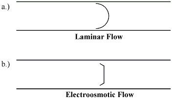
The efficiency of capillary electrophoresis separations is typically much higher than the efficiency of other separation techniques like HPLC. Unlike HPLC, in capillary electrophoresis there is no mass transfer between phases. In addition, the flow profile in EOF-driven systems is flat, rather than the rounded laminar flow profile characteristic of the pressure-driven flow in chromatography columns as shown in figure 5. As a result, EOF does not significantly contribute to band broadening as in pressure-driven chromatography. Capillary electrophoresis separations can have several hundred thousand theoretical plates.
The resolution (
According to this equation, maximum resolution is reached when the electrophoretic and electroosmotic mobilities are similar in magnitude and opposite in sign. In addition, it can be seen that high resolution requires lower velocity and, correspondingly, increased analysis time.
Besides diffusion and Joule heating (discussed above), factors that may decrease the resolution in capillary electrophoresis from the theoretical limits in the above equation include, but are not limited to, the finite widths of the injection plug and detection window; interactions between the analyte and the capillary wall; instrumental non-idealities such as a slight difference in height of the fluid reservoirs leading to siphoning; irregularities in the electric field due to, e.g., imperfectly cut capillary ends; depletion of buffering capacity in the reservoirs; and electrodispersion (when an analyte has higher conductivity than the background electrolyte). Identifying and minimizing the numerous sources of band broadening is key to successful method development in capillary electrophoresis, with the objective of approaching as close as possible to the ideal of diffusion-limited resolution.
Applications
Capillary electrophoresis may be used for the simultaneous determination of the ions NH4+,, Na+, K+, Mg2+ and Ca2+ in saliva.