
Established 1974 Founded 1974 | Phone +44 1274 435900 | |
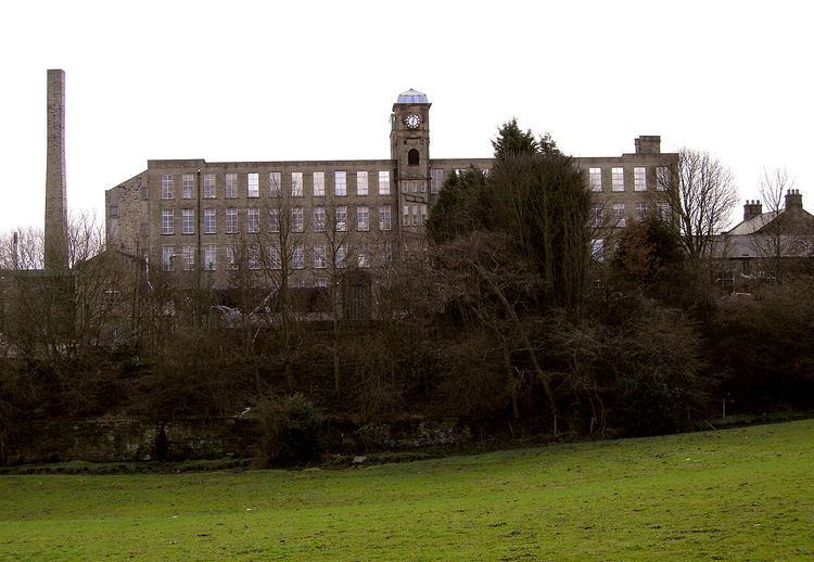 | ||
Type Industrial museum, Mill museum, Textile museum, Address Moorside Mills, Moorside Rd, Bradford BD2 3HP, UK Hours Open today · 11AM–4PMSaturday11AM–4PMSunday11AM–4PMMondayClosedTuesday10AM–4PMWednesday10AM–4PMThursday10AM–4PMFriday10AM–4PM Similar | ||
Bradford Industrial Museum, established 1974 in Moorside Mills, Eccleshill, Bradford, United Kingdom, specializes in relics of local industry, especially printing and textile machinery, kept in working condition for regular demonstrations to the public. There is a Horse Emporium in the old canteen block plus a shop in the mill, and entry is free of charge.
Contents
- Bradford industrial museum west yorkshire filmed in the early 90 s
- History of the site
- Motive power
- Transport
- First floor textile galleries
- Preparing
- Combing
- Drawing
- Spinning
- Weaving gallery
- Domestic looms
- Power looms
- Outside
- Stables
- Temporary exhibitions and events
- More images
- References
Bradford industrial museum west yorkshire filmed in the early 90 s
History of the site
In Yorkshire, a mill is a textile factory. The original mill was built by John Moore in 1875 for worsted spinning. In 1919 the clock tower was built as a war memorial to those lost in World War I, and two floors were added. The mill was later sold to W & J Whitehead, who ran the ring spinning machine which is still in the spinning gallery. In 1970 Bradford Council bought the mill and it opened as a museum on 14 December 1974.
Motive power
Here is machinery from the 19th century Industrial Revolution, including waterwheels, steam engines, oil engines and gas engines; plus an engineer's workshop display. There is a demonstration of the working machines several times a week (steam on Wednesdays only): contact the Museum for current demonstration times. The millstone is from Castlefields corn mill near Bingley; it is a bedstone carved from local millstone grit. A spindle passes through this and a similar upper runner stone; the grain enters via the spindle hole and is ground by the scissor-action of the grooves when the runner stone rotates against the bedstone. The grain is forced out at the outer edges as flour, then flows into a sack. The prime exhibit, a uniflow steam engine rescued from Linton mill and known as the Linton engine, was one of the last Bradford-made steam engines. There is a display explaining the history of steam power.
Transport
Most of the space is taken up with several examples of cars and light commercial vans built by the Jowett company of Bradford, Scott motor bikes and Baines bicycles. A Wallis & Steevens Advance type Steam Roller no. 7986 built in 1928 that was owned by Bradford City Council roads department and carries the council crest on the water tanks.
The Biggest exhibit is a locomotive named Nellie, after Nellie Crane the vicar's wife. Nellie is an 0-4-0 saddle tank industrial locomotive 1435, one of two built by Hudswell Clarke in Leeds in 1922 for the Esholt sewage works. When the works were being built, she carried excavated material, and thereafter coal and construction material, then coal and other materials until 1970 when she was loaned to the Yorkshire Dales Railway Society at Skipton. Her size is ca.23 x 8 x 11 ft, and she weighs 28 tons. The boiler works at 160psi, and she carries 700 gallons in the saddle water tank. The cylinders are 40-inch diameter 20-inch stroke operated by Stephenson's open link valve gear. A British Railways Crane Wagon is on display outside near the museum gates.
In the tram shed is the only tramcar left in Bradford, and a Bradford trolleybus. The first horse-drawn trams were introduced in 1882, followed by steam trams in 1883 and electric trams in 1898. Trolleybuses ran in Bradford from 1911 to 1972. There are various models of trams, including no. 237, built in Shipley in 1904, but shown as it was in 1912 with top deck extended and covered to accommodate 38 passengers. From 1904 to 1908 this tram travelled between Baildon bridge and Greengates. After that it was transferred to the Great Horton system, then went between Saltaire and Undercliffe. However its routes were limited as it was too tall to pass under the railway bridge at Eccleshill station.
Here are different types of old machines in working condition; plus printing equipment. There is a demonstration of the working machines on Wednesdays: contact the museum for current demonstration times.
This gallery holds machinery from the last of the hot metal typesetting printshops as used in the newspaper industry. The monotype keyboard produces punched 31-level tape for casting on the monotype caster. The keyboard comprises seven QWERTY arrangements (Roman upper and lower case, bold upper and lower case, italic upper and lower case and SMALL CAPITALS). It is operated by compressed air and produces a wide paper tape that contains perforations that when transferred to the caster give full instructions for each character to be cast. The monotype system was widely used in the commercial printing sector. There is a forme (text lines produced on a Linotype typesetting machine) made up into the front page of the last edition of the Yorkshire Sports, 2 May 1981. The assembled forme is ready to be moulded and cast into a curved printing plate.
There is a display of lead glyphs for typesetting. These would be set into a forme so that the text read backwards and upside down, then inked and pressed against paper using a platen in a printing press. The display includes various kinds of printing presses, including a Wharfedale stop cylinder press.
First floor textile galleries
In the 19th century, Bradford was famous for its worsted cloth, although life was hard for the workers. The displays show how a fleece was transformed through various stages into a suit. There is a demonstration of the working machines several times a week: contact the Museum for current demonstration times.
Preparing
Preparing is the process used in place of carding for long wools and hairs which would break on the card and therefore greatly reduce the quality of the worsted yarn produced. The maker-up or double-screw sheeting preparer is the first machine. This passes the fibre to and from delivery sheets via rollers, and ends with a lap of wool from six to eight feet long. The single screw can preparer is the most important machine of these, as it is here that the laps of wool or hair taken from the preceding boxes are prepared into a continuous sliver. The lap is placed on the feed sheet and carried forward to the back rollers. From the back rollers the fibres are delivered to the fallers, which with the aid of the front rollers, draw out the material into a continuous sliver. From the front rollers the sliver of fibres passes through a funnel, through the calender rollers and into a can which is placed directly underneath them. The material is now ready for the combing machine.
Combing
Combing straightens the fibres, isolates the long ones (tops) for spinning and discards the short ones (noil). There are various types of combing machines here, including the French comb, the Lister comb and the Holden comb. The Noble comb was the most popular as it would comb long, medium and fairly short staple wool, but the slivers needed special preparation in a punching machine beforehand.
French comb
In the French comb the slivers of wool are fed forward by ratchet-operated rollers and a pinned feed grid, the leading end of the fibres being pushed beyond the nipper jaws which open and shut to receive and hold them, leaving a fringe of fibres protruding through which the pins of the revolving cylinder comb pass, removing the short fibres or noil and any impurities. These are carried round to the underside and deposited in a box for removal. Whilst the above initial combing is taking place the drawing-off rollers, mounted on a carriage, move towards the nipper jaws and grip the fringe of fibres as soon as the last row of pins on the comb cylinder has passed through the fringe projecting from the nipper jaws. As the drawing-off rollers grip the projecting fringe, the intersector comb descends, piercing the fringe of fibres, the nipper jaws open and the fibres are given their second combing by the rotation and recession of the drawing-off rollers pulling the fibres through the pins of the intersector comb and the pins of the feed grid. The combed fibres are then conveyed by the leather apron of the drawing-off rollers to the front rollers of the carriage, down a funnel and through the calender rollers, into a can placed directly underneath.
Lister nip comb
This was used when the best results were wanted from long fibred wools and hairs such as mohair, alpaca, long English and crossbred wools. In the Lister comb, the slivers of wool or hair are fed into the machine over the back plate, through the fluted feed rollers, under the spreader roller and onto the pins of the fallers which disentangle and transport the fibres to the nip jaw. The nip jaw, with its swinging motion, closes in upon the fringe of fibres, grasping them and pulling them out from the faller pins; thus partially combing the fibres which are then received by the carrier comb and conveyed to the pins of the large combing circle into which they are pressed by the dabbing brush. As the large circle rotates, the unique feature of the machine, the side circle comb gives the fibres a secondary combing, removing not the short fibres, but any excessively long ones. The large comb circle carries the remaining fibres to the drawing-off rollers which give the fibres their final combing by removing the long fibres from the circle pins, with the short ones being left behind. The long fibres or top pass through a revolving funnel to the crimping box and into a can directly underneath. The short fibres or noils are removed from the pins of the large comb circle by lifting knives, and deposited into a can ready for removal.
Holden comb
The Holden comb was suited for the combing of short staple wools. The slivers of wool are fed into the machine through the feed guides to the filing head rollers and transferred to the pins of the comb circle by the lashing action of the filling heads. As the comb circle rotates, the fallers of the square motion rise, their pins piercing the fringe of fibres held in the comb circle by the keeper plate, and by drawing away give the fibres their initial combing. This removes any short fibres or noil and some long fibres termed robbings which are deposited in a box at the back of the square motion. As the comb circle carries the remaining fibres to the drawing-off head the fringe is penetrated by the pins of the intersecting or nacteur combs, the drawing-off rollers giving the fibres their final combing by removing the long fibres from the pins of the nacteur comb and the comb circle; the short ones being left behind. The long fibres or top pass through a revolving funnel to the coiler mechanism and into a can directly underneath. The short fibres or noils remaining in the nacteur combs are transferred to the comb circle by a small comb and removed with the noil in the comb circle pins by brushes and lifting knives and deposited into a box ready for removal.
Drawing
The machines, known as boxes, in the drawing section reduce the combed tops from thick slivers to thinner roving ready for spinning. This is done by drafting them between slow back rollers to faster front rollers, and controlling the fibres between these rollers. The first boxes where the ends are thickest are the double head can gill box (where the wool ends up in a can) and the 2-spindle gill box (where the wool ends up twisted and on spindles). On these machines the rollers are heavily fluted to control the sliver, and the front rollers padded with leather to cushion the wool. Between the front and back rollers are fallers or bars which control the roving by holding it with fine pins. The roving is now called slubbing which needs twist for strength, and is dealt with by a second set of boxes: a 2-spindle draw-box, 4-spindle weigh box, 8-spindle finisher/reducer and 8-spindle rover. In these boxes the principle of two sets of rollers with controlled fibre in between is the same, but the yarn is now twisted onto a bobbin via a flyer.
Finishing
The combed slivers produced on any type of combing machine are passed through a process known as finishing. This process takes place in a series of gill boxes in which the fibres are redistributed, the slivers made uniform in thickness and moisture added in order to give the wool its natural suppleness and condition. Blending is done where necessary to keep the top up to a given standard of quality and, if dyed, consistency of colour. The top ball produced is suitable for packing for transport and unwinding. The top represents the wool comber's finished product, and it is in this form that the wool is bought and sold as the spinner's raw material.
Spinning
Spinning is the final stage in converting wool to worsted yarns, the roving being drawn out to its final thickness and twist added for strength. There are three types of spinning machine or frame in common use in the United Kingdom, namely flyer, cap and ring. Another machine used for spinning worsted yarns is the worsted mule. All three types of machine or frame are similar in their method of drawing out or drafting the roving to make the required count or thickness, but differ in the way in which twist is imparted and the yarn wound onto the bobbin. Drafting takes place between the back and front rollers. The front rollers revolve faster than the back ones, drawing out the roving to the fineness of yarn required. Between the rollers are carriers which support and help to control the fibres as they are being drafted.
120-spindle flyer spinner
The flyer is the original type of mechanical spinning frame and is believed to be a direct development of the Saxony wheel used in hand spinning. It is suitable for producing thick smooth yarns from coarse quality wools and hairs, but is falling into disuse because of the low speed at which the spindles have to run. As the yarn leaves the front rollers it is guided through a porcelain ring to the top of a revolving spindle, around and down one of the arms of the flyer and onto the bobbin. The bobbin is carried on a lifter plate and moves up and down the spindle. As the flyer revolves, imparting twist to the yarn, the bobbin which is free to rotate on the spindle is pulled round by the spun yarn. A felt or cloth washer is placed between the lifter plate and bobbin to retard the revolving bobbin and create adequate yarn tension for the flyer to wind the yarn evenly on the bobbin. When the bobbins are full they are removed and replaced by empty ones. This action is termed doffing and is done manually on this machine.
122-spindle flyer twister
Twisting is the process in which two or more single-spun yarns are united to produce a yarn of greater strength for use as warp threads in the weaving process and for normal knitting purposes. This is done by rollers delivering the yarns to a revolving spindle which twists or folds the single yarns around one another. The machines used are similar to spinning frames in their method of applying twist, but differ in that they have only one set of delivery rollers instead of the usual complement of drafting rollers. This machine is an early example of a flyer twisting frame. On the flyer twister, twist imparted to the yarn in a similar manner as on the flyer spinner. A weighted band, running in a groove at the base of the bobbin, retards the revolving bobbin creating enough tension for the flyer to wind the yarn evenly onto the bobbin. The machine is hand doffed.
64-spindle cap spinner
The introduction of the cap frame ca.1828 was a step forward in attaining higher production and finer yarn spinning. It is suitable for producing yarns made from botany and fine crossbred quality wools. Unlike the flyer frame where the spindle and flyer rotate, on the cap frame the spindle is stationary and carries a steel cap. Moving up and down the spindle is a lifter plate which carries the spinning tube on which the bobbin fits. The revolving tube and bobbin impart twist to the yarn until it becomes strong enough to wind onto the bobbin. The speed of the bobbin causes the thread to balloon, and the air resistance to this balloon, combined with friction on the cap edge, is sufficient to give enough tension for winding on at the line of the cap edge as the bobbin moves up and down inside the cap. This machine is hand doffed.
24-spindle velox ring spinner
This is a later development of the ring spinning frame. The passage of the yarn from the front rollers to the paper tube - used in place of a bobbin - is different from other types of spinning frames. When the yarn leaves the rollers it passes direct to the top of an elongated spindle and coils round it two or three times before forming a balloon to the ring traveller. This enables the twist to be imparted between the spindle top and roller nip, thus helping to produce a smoother yarn.
Weaving gallery
The era of Industrial Revolution weaving machinery gave rise to technological jargon in places such as Yorkshire with a strong local dialect. The resultant inscrutability of linguistic terms has given rise to such jokes as the one from Monty Python's Trouble at Mill sketch: One on't cross beams gone owt askew on treadle. This nonsense may have been written so on the script as a joke, but what Graham Chapman could have said correctly in dialect is, "One o't crossbeams 'as gone out o' skew on't treadle", meaning "One of the crossbeams has gone askew on the treadle". The treadle was a rocking pedal, powered by the worker's foot. The treadle in turn powered a reciprocating beam, and the power from that was transferred to the machinery. On a loom, these reciprocating beams were called lams, and were connected with the treadles by strings which were also connected with jacks to work the yelds. In big factories, power could be transferred from one large drive wheel to another across a wide room via a reciprocating beam, called in that situation a crossbeam. Out of skew is a dialect expression meaning in incorrect position. Whether a foot-driven treadle could power a mighty crossbeam is a moot point, and may be a joke in itself, but the explanation of the above phrase and its humour is tightly connected with the mechanism of the weaving machinery described below.
Domestic looms
The hand loom with the witch is typical of many that were used in the mills by cloth designers to develop new fabric designs and patterns. They are still used in the textile departments of universities and colleges for training students in weaving and the designing of fabrics. The shafts are lifted by a witch, an early form of dobby, with weights underneath to pull the shafts down, and can work up to 50 shafts to produce very complicated patterns. The weft is put in by hand using the flying shuttle method invented in 1733 by John Kay, and up to four colours can be woven in the weft using Robert Kay's (son of John Kay) 1760 invention of the multiple shuttle box. On this simple-to-operate loom the designer is able to explore the application of new design ideas before beginning production trials on a wider loom. Many of the designs for woven fabrics made today were developed and created long ago on similar narrow-width pattern looms.
The hand loom with jacquard is a wooden hand loom typical of the many thousands of looms that were used in the domestic cottage industry throughout the British Isles. They were gradually replaced by all-metal looms (see the Hattersley domestic loom) and new methods of working practice, such as the factory system, during the Industrial Revolution. The loom has a four-shuttle drop box to weave up to four colours of weft, and has John Kay's flying shuttle method of inserting the weft. Most of the handlooms used in the home were ordinary shaft looms. These do not require roof space and would be weaving standard cloths, unlike this loom which is fitted with a 360 hook de Vogue jacquard and can weave very complex fabrics.
The plain Hattersley Domestic Loom was specially developed for cottage or home use and designed to replace the wooden handloom; the Domestic is similar in construction to a power loom. It was introduced ca.1900 and the makers claimed that a speed of 160 picks per minute could be easily attained with from 2 to 8 shafts weaving a variety of fabrics. Because foot pedals, or treadles, operate the loom it is still classed as a handloom, but it is much easier and faster to weave as all the motions of the loom are connected via crankshaft and gear wheels. Because the loom is designed to use only one shuttle when weaving, giving a solid colour in the weft, it is termed a plain loom. The cast metal chair, manufactured along with the loom, can be raised or lowered to suit, and the seat rocks forward and back as the weaver treadles the loom.
Power looms
The Hattersley 6 x 1 revolving skip box: this dress goods loom, used for the weaving of suiting fabrics etc., is fitted with a negative V or angle dobby, a development of the original invented by Hattersley's in 1867. Known throughout the textile industry as the Keighley dobby, it has since been copied, modified and manufactured in a variety of different forms. Hattersley also invented, in 1868, the skip box: a development of the circular or revolving box. This allowed the shuttle box to bypass or skip the next compartment along and pick out the shuttle of the following one.
The Dobcross H.K. box loom was manufactured in ca.1950 by Hutchinson, Hollingworth & Co. Ltd of Dobcross, Oldham. This loom was claimed by its makers to be one of the most widely used power looms in the woollen and worsted industries. It was used, with minor adaptations, for weaving goods as varied as light tropical suiting, costume cloths, overcoatings, army and police uniform cloths and heavy blankets. The main feature of this loom is the dobby (located top right of the loom with the hand wheel) which is known as the Knowles, American or positive wheel dobby. This device lifts and lowers the wooden shafts through which the warp ends are threaded, separating the warp threads to produce the shed. The loom has four rising or drop boxes at each side, which can be moved independently, and can weave up to seven shuttles, each with a different colour.
The Sowden worsted coating loom: as in all mechanical devices, there is drive to improve efficiency, and this loom has several patent innovations. For example, the 28 shaft negative square dobby is similar in construction to Hattersley's Keighley dobby. However, to allow the shuttle more time to pass through the shed the dobby has special curved slots that allow the shafts to dwell or remain open for longer. In addition, the pattern chain or lags controlling the shafts can be set to control all 28 shafts, or set to operate the first sixteen shafts to weave the cloth and the remaining twelve shafts to produce a name list or selvedge. The word selvedge is derived from self-edge, the edge of the cloth where the weft is turned back as it returns through the shed. The selvedge would often have a brand name or the country of origin woven into it. On the left side of the loom is the patent four-shuttle drop box motion incorporating a foot pedal. This is part of an escape mechanism in case the shuttle becomes trapped.
Outside
The mill's first owner, John Moore, lived at Moorside House with his family until 1887, followed by the later owners of Moorside Mills. The house interior is now a museum display, furnished as if the 19th century mill-owners were still living there. Gaythorne Row is a row of Victorian back-to-backs. It was rebuilt here in 1986, and is now furnished as for mill workers of the 1870s, 1940s and 1950s.
The Horse Emporium was once the mill's canteen block. The displays are arranged on the theme of horse power. Among other exhibits there is a heavy-duty British Railways dray, a decorative chaff cutter and a horse fodder measure. There is a saddler-at-work display, plus horse brasses, horseshoes and other harness. In a stable there is a blacksmith's workshop and farriery display, complete with many horseshoes, anvils, and metalworking tools.
Stables
This building was a 1918 motor car garage. At one end it contains restored horse-drawn vehicles. There is a reproduction of an 1890 garden seat omnibus, with wooden, slatted seats on top, like garden seats. These vehicles have not been used in the UK since 1931. This reproduction has hydraulic disc brakes for safety. There is a brougham, a 19th-century gentleman's light one-horse carriage. This design is said to have been named after Lord Chancellor Brougham in the early 19th century. There is also a steamer, or Shand-Manson steam fire pump of ca.1880. A team of horses pulled it, and steam powered it, at 250 gallons per minute. Firemen could get it ready in 7 minutes. It was successful enough for the manufacturers to export it worldwide - for example to the Warsaw Fire Guard - but it was expensive in coal and horses, and was superseded by motor pumps in ca.1900.
Temporary exhibitions and events
There are living history events, family activity days, and a yearly Victorian-style Christmas craft market. There are regular temporary exhibitions; in 2003, for example, there was a motorcycle exhibition, and in 2009 there was a rag-rug display. There are educational workshops for school and other groups, including Victorian classroom, World War II classroom and washday sessions.
From 7 December 2013 to the 16th November 2014 the museum held an exhibition titled ' A Masonic Experience '. Organised Freemasonry began with the formation of the Grand Lodge of England in 1717, a social fraternity grew out of operative Masonic guilds. This community exhibition will include a replica of a Masonic Lodge, a funnel fragment from a Falklands warship, and a colourful display of Masonic aprons, banners, glassware and ceramics.
One of the exhibition's centrepieces was a sumptuous robe worn by Sarastro in The Royal Opera House London's production of Mozart's The Magic Flute. Mozart became a Freemason in 1784 and several of his works, including The Magic Flute, are believed to have Masonic aspects.