
 | ||
Blade solidity is an important design parameter for the axial flow impeller and is defined as the ratio of blade chord length to pitch.
Contents
Where
In case of an axial flow impeller mean radius is defined in terms of hub (
Blade solidity affects various turbomachinery parameters. So to vary those parameters one needs to vary blade solidity but there are some limitations imposed by Aspect ratio (wing) (span/chord), pitch. If an impeller has few blades i.e high pitch it will result in less lift force and in a similar manner for more blades i.e. very low pitch, there will be high drag force.
Blade solidity should not be confused with rotor solidity, which is the ratio of the total area of the rotor blades to the swept area of the rotor.
Flow over isolated airfoil
Blade solidity is an important parameter that inter relates turbomachine parameter to airfoil parameter .Lift and drag coefficient for an airfoil is inter related to blade solidity as shown :
where
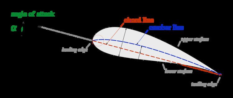
In an airfoil the mean line curvature is designed to change the flow direction ,the vane thickness is for strength and the streamlined shape is to delay the onset of boundary layer separation, taking all the design factors of an airfoil resulting forces of lift and drag can be expressed in terms of lift and drag coefficient.
Preliminary design procedure
Design of the impeller depends on specific speed, hub-tip ratio and solidity ratio. To illustrate the dependence, an expression for axial flow pump and fan is shown
where
Cordier diagram can be used to determine specific speed and impeller tip diameter
Solidity ratio generally falls in the range of 0.4-1.1