
 | ||
A beam splitter is an optical device that splits a beam of light in two. It is the crucial part of most interferometers.
Contents
Beam splitter designs
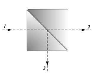
In its most common form, a cube, it is made from two triangular glass prisms which are glued together at their base using polyester, epoxy, or urethane-based adhesives. The thickness of the resin layer is adjusted such that (for a certain wavelength) half of the light incident through one "port" (i.e., face of the cube) is reflected and the other half is transmitted due to frustrated total internal reflection. Polarizing beam splitters, such as the Wollaston prism, use birefringent materials, splitting light into beams of differing polarization.
Another design is the use of a half-silvered mirror, a sheet of glass or plastic with a transparently thin coating of metal, now usually aluminium deposited from aluminium vapor. The thickness of the deposit is controlled so that part (typically half) of the light which is incident at a 45-degree angle and not absorbed by the coating is transmitted, and the remainder is reflected. A very thin half-silvered mirror used in photography is often called a pellicle mirror. To reduce loss of light due to absorption by the reflective coating, so-called "swiss cheese" beam splitter mirrors have been used. Originally, these were sheets of highly polished metal perforated with holes to obtain the desired ratio of reflection to transmission. Later, metal was sputtered onto glass so as to form a discontinuous coating, or small areas of a continuous coating were removed by chemical or mechanical action to produce a very literally "half-silvered" surface.
Instead of a metallic coating, a dichroic optical coating may be used. Depending on its characteristics, the ratio of reflection to transmission will vary as a function of the wavelength of the incident light. Dichroic mirrors are used in some ellipsoidal reflector spotlights to split off unwanted infrared (heat) radiation, and as output couplers in laser construction.
A third version of the beam splitter is a dichroic mirrored prism assembly which uses dichroic optical coatings to divide an incoming light beam into a number of spectrally distinct output beams. Such a device was used in three-pickup-tube color television cameras and the three-strip Technicolor movie camera. It is currently used in modern three-CCD cameras. An optically similar system is used in reverse as a beam-combiner in three-LCD projectors, in which light from three separate monochrome LCD displays is combined into a single full-color image for projection.
Beam splitters with single mode fiber for PON networks use the single mode behavior to split the beam. The splitter is done by physically splicing two fibers "together" as an X.
Arrangements of mirrors or prisms used as camera attachments to photograph stereoscopic image pairs with one lens and one exposure are sometimes called "beam splitters", but that is a misnomer, as they are effectively a pair of periscopes redirecting rays of light which are already non-coincident. In some very uncommon attachments for stereoscopic photography, mirrors or prism blocks similar to beam splitters perform the opposite function, superimposing views of the subject from two different perspectives through color filters to allow the direct production of an anaglyph 3D image, or through rapidly alternating shutters to record sequential field 3D video.
Phase shift
A beam splitter that consists of a glass plate with a reflective dielectric coating on one side gives a phase shift of 0 or π, depending on the side from which it is incident (see figure). Transmitted waves have no phase shift. Reflected waves entering from the reflective side (red) are phase-shifted by π, whereas reflected waves entering from the glass side (blue) have no phase shift. This is due to the Fresnel equations, according to which reflection causes a phase shift only when light passing through a material of low refractive index is reflected at a material of high refractive index. This is the case in the transition of air to reflector, but not from glass to reflector (given that the refractive index of the reflector is in between that of glass and that of air).
This does not apply to partial reflection by conductive (metallic) coatings, where other phase shifts occur in all paths (reflected and transmitted).
Classical lossless beam splitter
We consider a classical lossless beam-splitter with electric fields incident at both its inputs. The two output fields Ec and Ed are linearly related to the inputs through
where the 2 × 2 element is the beam-splitter matrix. r and t are the reflectance and transmittance along a particular path through the beam-splitter, that path being indicated by the subscripts.
Assuming the beam-splitter removes no energy from the light beams, the total output energy can be equated with the total input energy, reading
Requiring this energy conservation brings about the relationships between reflectance and transmittance
and
where "
Further simplifying we obtain the relationship
which is true when
where substitutions of the form
and similarly,
It follows that
Now that the constraints describing a lossless beam-splitter have been determined, we can rewrite our initial expression as
Use in experiments
Several experiments in quantum theory and relativity theory and other fields of physics use beam splitters (usually in interferometers); these include:
Quantum mechanical description
We consider two single mode input fields, denoted by the annihilation operators
In order to obtain the entries of the transformation matrix one must take into account that the commutation relations of the fields' hold. As is well-known from second quantization, one must make sure that
and
This, together with energy conservation yields the following set of constraints:
For a dielectric 50:50 beam splitter the reflected and transmitted beams differ in phase by
The unitary transformation associated with this transformation is
Using this unitary, one can also write the transforms as
Application for quantum computing
In 2000 Knill, Laflamme and Milburn (KLM protocol) proved that it is possible to create universal quantum computer solely with beam splitters, phase shifters, photodetectors and single photon sources. The states that form a qubit in this protocol are the one photon states of two modes, i.e. the states |01> and |10> in the occupation number representation (Fock state) of two modes. Using these resources it is possible to implement any single qubit gate and 2-qubit probabilistic gates. The beam splitter is an essential component in this scheme since it is the only one that creates entanglement between the Fock states.