
 | ||
An Audio Analyzer is a test and measurement instrument used to objectively quantify the audio performance of electronic and electro-acoustical devices. Audio quality metrics cover a wide variety of parameters, including level, gain, noise, harmonic and intermodulation distortion, frequency response, relative phase of signals, interchannel crosstalk, and more. In addition, many manufacturers have requirements for behavior and connectivity of audio devices that require specific tests and confirmations.
Contents
- History
- Block Diagram and Operation
- Electro acoustic Devices
- Audio Generator
- Signal Analyzer
- Measurements and Results
- References
Audio analysis requires that the device under test receive a stimulus signal of known characteristics, with which the output signal (response) may be compared by the analyzer in order to determine differences expressed in the specific measurements. This signal may be generated or controlled by the analyzer itself or may come from another source (e.g., a recording) as long as characteristics relative to the desired measurement are defined.
As test and measurement equipment, audio analyzers are required to provide performance well beyond that of the typical devices under test (DUTs). High quality audio analyzers must demonstrate vanishingly low levels of noise, distortion and interference in order to be deemed worthwhile, and must do so consistently and reliably to be trusted by engineers and designers. For example, while a commercial CD player can achieve a total harmonic distortion plus noise (THD+N) ratio of approximately -98 dB at 1 kHz, a high quality audio analyzer may exhibit THD+N as low as -121 dB (this is the claimed performance of the Audio Precision APx555).
Audio Analyzers find use in both development and production of products. A design engineer will find it very useful when understanding and refining product performance, while a production engineer will wish to perform tests to rapidly confirm that units meet specifications. Very often audio analyzers are optimized for one of these two cases.
Current popular audio analyzer models include: APx585 and APx555 (from Audio Precision), dScope Series III (from Prism Sound), U8903A (from Agilent) and the UPP and UPV analyzers (from Rohde & Schwarz).
History
One of the earliest reliable sources used for audio test was the first product made by Hewlett-Packard in 1939, the HP200A audio oscillator. The clever and inexpensive design of the HP200A allowed testers to generate very high quality, low distortion sine waves that could be used for testing. This was followed by the company's introduction of the HP320A and HP320B Distortion Analyzers in 1941.
These early analyzers could only determine total harmonic distortion and noise combined, and worked by employing a steep notch filter to remove the fundamental frequency of the stimulus signal from the output of the DUT. The remaining signal was measured as an AC voltage, and thus allowed for the manual calculation of total noise and distortion to approximately 0.1% minimum.
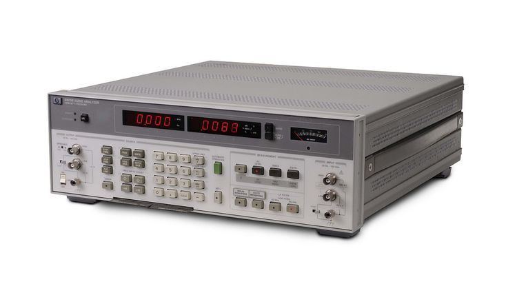
Subsequent products from HP, Wandell & Goltermann, Radford, Marconi, Sound Technology, and Amber continued to refine measurement capabilities from the 1950s through the 1970s, but the model of usage remained relatively constant; signal generators and analyzers were separate pieces of equipment, and testing involved careful tuning of each one by a person with high technical skills. This changed in 1980 with the introduction of the Tektronix AA501 Distortion Analyzer, which automated the processes of setting levels, frequency tuning and nulling. At this same time Hewlett-Packard introduced the popular HP8903B, which combined a high quality signal generator and analyzer in a single unit.
By the mid-eighties, Tektronix ceased production of audio test equipment, and in 1984 members of the team that had developed the AA501 started Audio Precision. The first Audio Precision product was the System One, which combined an integrated generator and analyzer with a connected PC to fully automate test procedures and provide a much higher degree of computational power than the simple microprocessors used in other products at the time. The novel use of a PC allowed for a high degree of custom automation and enabled a radically different visual presentation of results.
The combination of PC technology with audio analyzers was adopted by others, including Prism Sound (dScope), Rohde and Schwarz (UPL), and Stanford Research (SR1). As the power of available PCs increased, measurements themselves migrated from being performed internally by audio analyzers to applications running on connected PCs performing FFT (Fast Fourier Transform) calculations, greatly increasing the flexibility and resolution of many results.
In addition to analog, audio analyzers today are frequently capable of generating and measuring audio signals over several different types of digital I/O. For example, the Rohde and Schwarz UPP offers AES/EBU, S/PDIF, I²S and HDMI options; the Audio Precision APx500 Series analyzers support AES/EBU, S/PDIF, I²S, HDMI, PDM (Pulse Density Modulation), and Bluetooth radio, and are fully DSP based.
Block Diagram and Operation
A modern audio analyzer consists of:
In a closed-loop test, the analysis engine controls the audio generator while simultaneously measuring the output of the DUT, as shown below:
The signal analyzer can provide control to both the audio generator and the audio input stages, assuring that test conditions are met. This also permits precise time relationships between the stimulus and response of a DUT to be determined.
In an open-loop test, the signal analyzer has no control over the audio source driving the DUT, and thus the user must take care to ensure that the source is providing a signal of appropriate characteristics. Open loop tests are useful for measuring DUTs that have no direct signal input, such as a CD or MP3 player.
Electro-acoustic Devices
Electro-acoustic devices such as loudspeakers and microphones present special problems for analysis, as they must receive or transmit signals through air. In these cases, the DUT in the model shown above must be replaced with the complete electro-mechanical system, e.g., a power amplifier to drive a loudspeaker, a loudspeaker, a measurement microphone and microphone pre-amplifier. The actual device under test can be measured only when the other devices in this system are fully characterized, so that the contributions from these devices may be subtracted from the response. Many modern audio analyzers contain measurement sequences that automate this procedure, and the focus of recent developments has been on quasi-anechoic measurements. These techniques allow loudspeakers to be characterised in a non-ideal (noisy) environment, without the need for an anechoic chamber, which makes them ideally suited for use in high volume production line manufacturing. Most quasi-anechoic measurements are based around an impulse response created from a sine wave whose frequency is swept on a logarithmic scale, with a window function applied to remove any acoustic reflections. The log swept sine method increases signal-to-noise ratio and also allows measurement of individual distortion harmonics up to the Nyquist frequency, something which previously impossible with older analysis techniques such as MLS (Maximum Length Sequence).
Audio Generator
An audio generator suitable for use in test and measurement must meet several criteria that apply to both analog and digital stimulus:
Additionally, the generator will allow for the definition of a precise frequency range and amplitude of the stimulus presented to the DUT. This is critical when aligning test conditions to the characteristics of the DUT.
Signal Analyzer
Prior to the introduction of integrated audio analyzers, audio generators and audio analyzers were separate pieces of equipment. In this article, signal analyzer refers to the element of a modern audio analyzer that implements the actual measurements.
Whether realized in analog circuits, digital signal processing (DSP) or FFT, the analyzer engine must provide high precision implementations of:
As most modern instruments are digitally based, signal analysis is frequently performed using FFT-based calculations, allowing many results to be calculated in a single test pass.
Results of these measurements are processed by the analyzer into readable data using a variety of standard units and formats, such as volts, dB, dBu, SPL, ohms, relative percentage, etc., depending upon the specific measurement being reported. Derived results are achieved by combining several primary results into a calculated result.
Measurements and Results
Audio analyzers are capable of measuring many types of parameters. The fundamental measurements are: