
Hot pluggable yes Pins 9 | External yes Connector D-subminiature | |
 | ||
Type Human input device interface Designed 1977; 40 years ago (1977) | ||
The Atari joystick port is a widely used computer port used to connect various gaming controllers to game console and home computer systems. It was originally introduced on the Atari 2600 in 1977 and then used on the Atari 400 and 800 in 1979. It went cross-platform with the Commodore VIC-20 of 1981, and was then used on many following machines from both companies, as well as a growing list of 3rd party machines like the MSX platform and various Sega consoles.
Contents
- History
- Description
- Joysticks
- Driving controllers
- Paddles
- Keyboard controllers
- Light pen
- Graphics tablets
- Output
- Fully compatible systems
- Semi compatible systems
- Systems using adaptors
- References
The port, based on the inexpensive 9-pin D-connector, became a de facto standard through the 1980s and into the 1990s, supported by a wide variety of joysticks and other devices, most commonly paddle controllers, light pens and computer mice. The standard was so engrained that it led to devices like the Kempston Interface that allowed Atari joysticks to be used on the ZX Spectrum. The port was also used for all sorts of non-gaming roles, including the AtariLab interface, modems, numeric keypads, and even a video expansion card.
By the mid-1990s the mouse had become a universal peripheral, and games used it as the primary controller where joysticks would have been used previously. Joysticks became used only for specific roles, typically flight simulators, and the Atari port disappeared from computers during this era.
History
The Atari 2600 developed out of an effort to address problems Atari found when releasing their first home video game console, Pong. Although successful, Pong was an expensive system to design, and was dedicated solely to one game. It would be much more practical to have a machine that could run multiple games. The list of games it would need to support included Pong variations, and Tank. It was the desire to run these two games that led to the need for some sort of flexible input system; Pong used analog paddle controllers, while Tank used dual digital (on/off) joysticks. Arcade games of the era generally used paddles, joysticks or a unique sort of steering wheel controller that was spun, entirely unlike a real car.
Development of the 2600 was strictly a paper project until September 1975, when the MOS Technology 6502 processor was released. The 6502 offered the right combinations of features, performance and price that made a console using ROM cartridges for program storage practical for the first time. Now that such a machine seemed like a real possibility, the design team at Cyan Engineering began serious development.
As part of this effort, Joe Decuir began development of an I/O system based primarily on the MOS Technology 6532, which included 8-bit I/O ports as well as the hardware needed to control memory refresh and similar housekeeping tasks. Ultimately, the design used five of the I/O ports (pins) to control the various front-panel switches, and four each for the two controllers. Additionally, the TIA, whose primary task was sound and video, was used to handle timing-based controllers like paddles and light pens. The physical interface was the 9-pin D-sub connector, which was already relatively common for reduced pin-count serial ports on the Apple II and S-100 bus machines. Each of the pins in the connector went directly to the appropriate pin on the associated chip.
The 2600 was released in 1977, shipping with both the paddle controllers and a single joystick. The port allowed the 2600 to more easily support a wider variety of games, not just specific games but entire genres. Most game consoles before the Atari had paddle controllers, even detachable ones in the case of the Fairchild Channel F and Magnavox Odyssey. But the joystick was new, and quickly garnered praise as it allowed direct input into a number of games that would otherwise be difficult to control using a paddle. The joystick has been called "the pinnacle of home entertainment controllers in its day".
After the release of the 2600, the Cyan team immediately turned to the development of its replacement, aiming for the 1979 time frame. As the "standard" was already set on the 2600, the new machines naturally used the same controller interface, although the details of the systems used to read it changed. As 1979 approached the home computer market emerged, and Atari repositioned the new system as the 400 and 800, the first members of the Atari 8-bit family. This meant the standard now crossed the line between consoles and computers.
The port design was extremely flexible, and over time saw not only a wide variety of input devices, but output as well. Included among the non-controller devices was the AtariLab system that allowed users to plug in various laboratory devices like digital thermometers, the 300 baud MPP-1000C modem, and even Atari's own 80-column adaptor for the 8-bit series, the XEP80. It was widely used in the home-brew market as a lightweight input device, and articles on how to build various adapters were common.
By the time Commodore began development of its replacement for the Commodore PET, millions of controllers using the system were in the market, some of those originally for 2600s that were no longer being actively used. Atari held no patents on the port itself, so it was an easy choice to pick it for the VIC-20. Atari did, however, have patents on the joystick itself, and ultimately won an injunction against Commodore, who had produced an almost identical "imitation" joystick for the VIC-20.
Now that the standard crossed company lines as well as markets, and it rapidly proliferated across the industry. Hundreds of new devices using the system cropped up over time, including trackballs and other advanced inputs.
The standard became so widely used that practically every 8-bit machine released after 1982 used it, and those that did not, like the Apple II, Texas Instruments TI-99/4A and Sinclair ZX Spectrum, provided an excellent market for 3rd party companies who produced adaptors. The port moved to 16/32-bit machines like the Atari ST and Commodore Amiga as well.
The introduction of the Nintendo Entertainment System was the first widespread example of a gaming system in that era that did not use the Atari design, its D-pad having been designed specifically to be less bulky. As newer consoles were released into the newly invigorated market, new port designs were introduced for every different model. Meanwhile, the IBM PC had introduced the 15-pin game port that was designed primarily for analog inputs, but use remained rare until the introduction of popular flight simulators.
By the 1990s, the Atari standard was largely dead. Even the Atari Jaguar did not use it. Nevertheless, it was so popular during its run that it remains a common staple in video game iconography to this day, and is commonly referred to as the symbol of the 1980s video game system and system design. There have also been numerous systems to allow the ports to be adapted to Universal Serial Bus, and even entirely new Atari-like joystick designs using USB.
Description
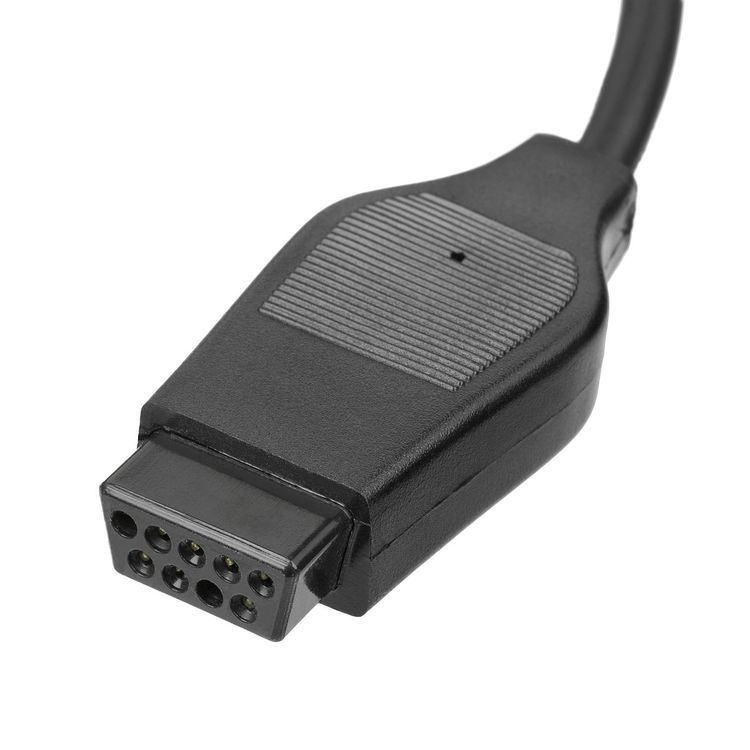
The Atari joystick port used a 9-pin male socket in the host system, and female connectors on the devices. Classic Atari peripherals used a teardrop shaped rounded plug that was easy to grip to make it easier to plug in. Almost all compatible devices used similar physical layouts, often to the point of copying the plug design outright.
In the Atari consoles and 8-bit computers, reading the stick inputs was handled by a polling process that set values in various 8-bit registers. In the 8-bit machines, for instance, the pins in the port were connected to custom I/O hardware. The instantaneous values were polled 30 times a second during the vertical blank interrupt (VBI) when the operating system (OS) handled a number of housekeeping tasks. Depending on settings in other registers, the inputs on the pins were interpreted in a number of ways and then the output data was placed in a number of RAM registers. Atari referred to this copying from hardware to the RAM as "shadowing".
Joysticks
Atari joysticks included four internal switches to encode direction, and a fifth for the trigger button. Each of these led directly to a pin in the port, and from there to an input on one of the I/O chips. The OS would read these inputs on each VBI, and then copy their status into the shadow registers, with the lower-numbered ports in the least significant bits. For instance, if stick 0 was being pushed up and to the right, the PORTA register would have bits 0 and 3 set, or decimal value 16. The status of each of the joystick's trigger buttons was instead placed in four separate registers, whose zero-bit would be set to 1 if the trigger was pushed.
Driving controllers
Driving games of the 1980s were generally top-down and used a unique controller that would cause the car to turn at a fixed rate to one side or the other or go in a straight line (Atari's Night Driver is a notable exception). These games were controlled not by a wheel that pointed left or right like in a real car, but a wheel that sent left or right commands only if it was actively spinning in that direction. Players would spin the wheel rapidly to get the car to turn as fast as possible in the desired direction, and then brake the wheel with their hands to go straight again.
Driving controllers were implemented on Atari consoles with a device that worked in the same fashion as the joysticks, pressing each directional switch in turn as it spun. Programs had to watch the sequence of bits in the shadow registers in order to tell if the controller was being spun to the right or left, the OS itself did not attempt to interpret this to provide "right" and "left" instructions for the programmer.
Paddles
Paddles are analog devices normally used to control horizontal positioning of the player on the screen.In 1976 the paddle worked by connecting the +5V line through a potentiometer that controlled the charging of a capacitor. When the voltage in the capacitor reached a threshold value, it caused an interrupt in the OS that copied the value of the color clock value from the video hardware. Normally this produced a value from 0 to 228 which was stored as an 8-bit value in the appropriate POT shadow register.
One advantage to this system was the color clock values provided by the paddle controllers were the same numbers that controlled the horizontal location of sprites, meaning that the programmer could simply copy the value of the pot shadow register into the sprite's horizontal position register and it would appear at the appropriate location on-screen.
Keyboard controllers
Keyboard controllers were used in the Atari systems as auxiliary inputs, for numeric keypads on the 8-bit machines and special purpose controllers on the 2600, like the Star Raiders port. They were based on a 4-by-3 matrix for a total of 12 possible keys. For any keypress, the row was encoded by setting one of four bits in the joystick shadow register, PORTA or PORTB, while the column set a bit on one of the trigger registers. The programmer then had to read both to determine which key was pressed, the OS itself did not map this back onto key codes (which the 2600 lacked anyway).
Light pen
Light pens were directly supported as well. In this case a photosensor in the light pen was connected to the trigger line of the port. If placed in light pen mode, whenever the trigger was seen to go high, the OS would copy the color clock value into the PENH register to record the horizontal position, and the VCOUNT register of the video hardware into the PENV register. The result was a set of two eight-bit values directly encoding the position of the pen in X and Y using the same coordinates as the video hardware. A sprite can then be set to those coordinates and will appear under the light pen. As the timers were not very accurate, the positions had to be averaged over several screens to produce a usable value.
Graphics tablets
Graphics tablets were handled using the same hardware as the paddle controllers, encoding the X axis as the output of one paddle and the Y axis as the other. There were three buttons, one on the stylus and one on either upper corner of the pad. The stylus button was connected to the up direction of the joystick port, while the left and right buttons on the tablet itself were connected to two of the trigger inputs.
Output
Because the pins of the joystick were wired directly to the input/output controllers on the motherboard, it was possible to program them to output to the port, rather than input. This capability was used in the Atari XEP80 80-column card, which used pin 1 as an output pin, and pin 2 as an input. A device driver used these pins to implement a bidirectional serial port, which worked in joystick port 1 or 2. Similar drivers were used by other devices, like modems, which avoided the need to use the more expensive Atari SIO system.
Fully compatible systems
The Commodore VIC-20 had one Control Port, and the C64 had two ports, each a complete implementation of the Atari standard. They differed from the Atari systems primarily in the hardware used to decode the inputs. For joystick inputs, Port A was read by the MOS Technology CIA, while Port B was connected to Parallel Port B on the MOS Technology PIA. The paddle inputs generated timed voltages in a fashion similar to the Atari, but was scanned by timers in the MOS Technology SID sound chip. The paddle triggers were read by the CIA. There was only one set of two timers for this purpose in the SID, so another register controlled which of the two ports was connected to the SID at any given instant. Light pens could only be used in Port A and worked in a similar way to the Atari, but was based on a faster clock so the horizontal axis read from 0 to 511. The accuracy was the same as the Atari however, as the values were rounded off to even values only.
As the CIA was also used for handling the keyboard and other housekeeping tasks, the dual-use on Port A led to some problems. For instance, the left direction switch of Port A was wired to the same input as the CTRL key on the keyboard, and when it was used it would cause scrolling in BASIC programs to slow down. Due to the way keyboard scanning was handled, holding down the trigger would cause random characters to be generated. As a result, many C64 games required the joystick to be plugged into Port B; this was handled by the PIA, which was generally unused during games.
On the Atari ST, the two ports were normally configured with Port 0 set to mouse mode and Port 1 to joystick. In joystick mode they operated largely identically to the earlier machines, but in mouse mode the system watched the ports for discrete inputs on the various directional pins, or "events". The mouse sensor generated 200 events for every inch of movement, and the system could track these fast enough to handle movements of up to 10 inches per second. Handling the ports, the keyboard and a real-time clock was a dedicated Intelligent Keyboard (ikbd) controller. It is not clear whether the ST had the analog inputs of the earlier machines.
The Amiga had a complete two-port implementation known as gameports. Unlike earlier systems that had to be interpreted by examining bits in registers, the Amiga's OS had a number of drivers and libraries that made interaction simple. This included handlers for five types of input devices, include mice, joysticks, light pens and "proportional controllers" as a catch-all for analog inputs like paddles and analog joysticks. They also had settings for how and when the OS would report changes. For instance, the programmer could set the drivers to only report when the mouse had moved at least 10 events, thus lowering how often they had to deal with mouse movement.
Semi-compatible systems
The TI-99/4 used a 9-pin connector that was physically identical to the Atari version, as well as being similar in terms of the devices and the way they worked. However, the port's pins were re-arranged, so it was not directly compatible. Converters allowing Atari-standard devices to be plugged in were both simple and very common.
MSX machines used a slightly modified version of the port, replacing one of the analog inputs with a second trigger, and the other with a strobe pin. Under normal operation, any Atari style joystick could be used, although it would lack the second trigger button. The strobe pin was used to support mouse input. Electrically, a mouse generates what is essentially a random stream of pulses as it moves. On systems like the ST and Amiga, custom hardware was used to carefully track these in order for the motion to be smoothly followed, as the CPU might become too busy with other tasks to follow the rapid interrupts. Less powerful 8-bit designs did not have the performance to smoothly track a mouse without additional hardware, and the MSX designs, based on off-the-shelf hardware, lacked this ability. Instead, the tracking hardware was moved into the mouse. The mice held two 8-bit values tracking the movement in X and Y since the last time they had been polled. To read the values out, the strobe pin was pulled high four times. With each pulse, a nibble of the two bytes was output on the four directional pins in serial fashion. The strobe pulse also reset the value to zero, starting the polling process over again. MSX mice were expensive, and this led to adaptors for PS/2 style mice, which operated along similar principles.
Systems using adaptors
The Apple II also had a joystick port using a 9-pin D-sub, but it was a very different system that connected two analog joysticks to a single port. These were not very suitable for directional games, and adapters for Atari port devices were common, both commercial ones like the Sirius Joyport, as well as many home-brew systems. Unlike the ports used on the Commodore systems, most of the homebrew systems only adapted the joystick, and generally did not include the other inputs. These adapters did not allow the analog inputs of paddles to be used, in spite of the port already handling these inputs directly meaning all that was needed was a mechanical adapter.
The Sinclair ZX Spectrum had no built-in controller port, which led to a profusion of different inputs. Atari port adapters were common, and several devices emerged including the Kempston Interface and ZX Interface 2 that were incompatible with each other. The Interface 2 turned joystick presses into keyboard presses, and thus could not generate the analog signals of the paddles.
The BBC Micro had a relatively complex port system which was based on a 15-pin D-connector that supported two analog joysticks like the ones on the Apple II. These ran to dedicated analog-to-digital circuitry, which made them excellent for the sort of interfacing tasks seen in (for instance) AtariLab. However, the popularity of the Atari port was such that adapters were also available for this system, varying widely in the number and types of control devices they supported.