
Country of origin United States Applications Manned lunar landing | Design life 75 hours (Extended) | |
 | ||
The Apollo Lunar Module (LM), originally designated the Lunar Excursion Module (LEM), was the lander portion of the Apollo spacecraft built for the US Apollo program by Grumman Aircraft to carry a crew of two from lunar orbit to the surface and back. Designed for lunar orbit rendezvous, it consisted of an ascent stage and descent stage, and was ferried to lunar orbit by its companion Command and Service Module (CSM), a separate spacecraft of approximately twice its mass, which also took the astronauts home to Earth. After completing its mission, the LM was discarded. It was capable of operation only in outer space; structurally and aerodynamically it was incapable of flight through the Earth's atmosphere. The Lunar Module was the first manned spacecraft to operate exclusively in the airless vacuum of space. It was the first, and to date only, crewed vehicle to land on a natural object in the solar system other than the Earth.
Contents
- Operational profile
- History
- Contract letting
- Design phase
- Astronaut training
- Development flights
- Production flights
- Extended J class missions
- Specifications
- Ascent stage
- Descent stage
- Apollo Telescope Mount
- LM Truck
- Depiction in film and television
- References
Six such craft successfully landed on the Moon between 1969 and 1972. A seventh provided propulsion and life support for the crew of Apollo 13 when their CSM was disabled by an oxygen tank explosion en route to the Moon.
The LM's development was plagued with problems which delayed its first unmanned flight by about ten months, and its first manned flight by about three months. Despite this, the LM eventually became the most reliable component of the Apollo/Saturn space vehicle, the only component never to suffer a failure that significantly affected a mission.
The total cost of the LM for development and the units produced was $21.3B in 2016 dollars, adjusting from a nominal total of $2.2B using the NASA New Start Inflation Indices.
Operational profile
At launch, the Lunar Module sat directly beneath the Command/Service Module (CSM) with legs folded, inside the Spacecraft-to-LM Adapter (SLA) attached to the S-IVB third stage of the Saturn V rocket. There it remained through earth parking orbit and the Trans Lunar Injection (TLI) rocket burn to send the craft toward the Moon.
Soon after TLI, the SLA opened and the CSM separated, turned around, came back to dock with the Lunar Module, and extracted it from the S-IVB. During the flight to the Moon, the docking hatches were opened and the LM Pilot entered the LM to temporarily power up and test its systems (except for propulsion). Throughout the flight, he performed the role of an engineering officer, responsible for monitoring the systems of both spacecraft.
After achieving a lunar parking orbit, the Commander and LM Pilot entered and powered up the LM, replaced the hatches and docking equipment, unfolded and locked its landing legs, and separated from the CSM, flying independently. The Commander operated the flight controls and engine throttle, while the Lunar Module Pilot operated other spacecraft systems and kept the Commander informed on systems status and navigational information. After visual inspection of the landing gear by the Command Module Pilot, the LM was withdrawn to a safe distance, then the descent engine was pointed forward into the direction of travel to perform the 30 second Descent Orbit Insertion burn to reduce speed and drop the LM's perilune to within approximately 50,000 feet (15 km) of the surface, about 260 nautical miles (480 km) uprange of the landing site.
At this point, the engine was started again for Powered Descent Initiation. During this time the crew flew on their backs, depending on the computer to slow the craft's forward and vertical velocity to near zero. Control was exercised with a combination of engine throttling and attitude thrusters, guided by the computer with the aid of landing radar. During the braking phase altitude decreased to approximately 10,000 feet (3.0 km), then the final approach phase went to approximately 700 feet (210 m). During final approach, the vehicle pitched over to a near-vertical position, allowing the crew to look forward and down to see the lunar surface for the first time. Finally the landing phase began, approximately 2,000 feet (0.61 km) uprange of the targeted landing site. At this point manual control was enabled for the Commander, and enough fuel reserve was allocated to allow approximately two minutes of hover time to survey where the computer was taking the craft and make any necessary corrections. (If necessary, landing could have been aborted at almost any time by jettisoning the descent stage and firing the ascent engine to climb back into orbit for an emergency return to the CSM.) Finally, 66 inch (1676 mm) long probes extending from three footpads of the lander touched the surface, activating the contact indicator light which signaled time for descent engine cutoff, allowing the LM to settle on the surface.
When ready to leave the Moon, the LM would separate the descent stage and fire the ascent engine to climb back into orbit, using the descent stage as a launch platform. After a few course correction burns, the LM would rendezvous with the CSM and dock for transfer of the crew and rock samples. Having completed its job, the LM was separated and sent into solar orbit or to crash into the Moon.
History
The Lunar Module (originally designated the Lunar Excursion Module, known by the acronym LEM) was designed after NASA chose to reach the Moon via Lunar Orbit Rendezvous (LOR) instead of the direct ascent or Earth Orbit Rendezvous (EOR) methods. Both direct ascent and EOR would have involved landing a much heavier, complete Apollo spacecraft on the Moon. Once the decision had been made to proceed using LOR, it became necessary to produce a separate craft capable of reaching the lunar surface and ascending back to lunar orbit.
Contract letting
In July 1962, eleven firms were invited to submit proposals for the LEM. Nine companies responded in September, answering 20 specific questions posed by the NASA RFP in a 60-page limited technical proposal. Grumman Aircraft was awarded the contract two months later. Grumman had begun lunar orbit rendezvous studies in the late 1950s and again in 1961. The contract cost was expected to be around $350 million. There were initially four major subcontractors—Bell Aerosystems (ascent engine), Hamilton Standard (environmental control systems), Marquardt (reaction control system) and TRW's Space Technology Laboratories (descent engine).
The Primary Guidance, Navigation and Control System (PGNCS) was developed by the MIT Instrumentation Laboratory; the Apollo Guidance Computer was manufactured by Raytheon (a similar guidance system was used in the Command Module). A backup navigation tool, the Abort Guidance System (AGS), was developed by TRW.
Design phase
The Lunar Module was chiefly designed by Grumman aerospace engineer Thomas J. Kelly. The first LEM design looked like a smaller version of the Apollo Command/Service Module (a cone-shaped cabin atop a cylindrical propulsion section) with folding legs. The second design invoked the idea of a helicopter cockpit with large curved windows and seats, to improve the astronauts' visibility for hover and landing. This also included a second, forward docking port, allowing the LEM crew to take an active role in docking with the CSM.
As the program continued, there were numerous redesigns to save weight, improve safety, and fix problems. First to go were the heavy cockpit windows, and the seats; the astronauts would stand while flying the LEM, supported by a cable and pulley system, with smaller triangular windows giving them sufficient visibility of the landing site. Later, the redundant forward docking port was removed, which meant the Command Pilot gave up active control of the docking to the Command Module Pilot; he could still see the approaching CSM through a small overhead window. These changes resulted in significant weight savings. Egress while wearing bulky Extra-Vehicular Activity (EVA) spacesuits was also facilitated by a simpler-opening forward hatch (32 x 32 inches).
A configuration freeze did not start until April 1963, when the ascent and descent engine designs were decided. In addition to Rocketdyne, a parallel program for the descent engine was ordered from Space Technology Laboratories (TRW) in July 1963, and by January 1965 the Rocketdyne contract was canceled.
Power was initially to be produced by fuel cells built by Pratt and Whitney similar to the CSM, but in March 1965 these were discarded in favor of an all-battery design.
The initial design had three landing legs. As any particular leg would have to carry the weight of the vehicle if it lands at any significant angle, three legs was the lightest configuration. However, it would be the least stable if one of the legs were damaged during landing. The next landing gear design iteration had five legs and was the most stable configuration for landing on an unknown terrain. That configuration, however, was too heavy and the designers compromised on four landing legs.
In June 1966, the name was changed to Lunar Module (LM), eliminating the word "excursion". According to George Low, Manager of the Apollo Spacecraft Program Office, this was because NASA was afraid that the word "excursion" might lend a frivolous note to Apollo. After the name change from "LEM" to "LM", the pronunciation of the abbreviation did not change, as the habit became ingrained among engineers, the astronauts, and the media to universally pronounce "LM" as "lem" which is easier than saying the letters individually.
Astronaut training
To allow astronauts to learn lunar landing techniques, NASA contracted Bell Aerosystems in 1964 to build the Lunar Landing Research Vehicle (LLRV), otherwise known as "The Flying Bedstead," which used a gimbal-mounted vertical jet engine to counter 5/6 of its weight to simulate the Moon's gravity, in addition to its own hydrogen peroxide thrusters to simulate the LM's descent engine and attitude control. Successful testing of two LLRV prototypes at the Dryden Flight Research Center led in 1966 to three production Lunar Landing Training Vehicles (LLTV) which along with the LLRV's were used to train the astronauts at the Houston Manned Spacecraft Center. This aircraft proved fairly dangerous to fly, as three of the five were destroyed in crashes. It was equipped with a rocket-powered ejection seat, so in each case the pilot survived, including the first man to walk on the Moon, Neil Armstrong.
Development flights
LM-1 was built to make the first unmanned flight for propulsion systems testing, launched into low Earth orbit atop a Saturn IB. This was originally planned for April 1967, to be followed by the first manned flight later that year. But the LM's development problems had been underestimated, and LM-1's flight was delayed until January 22, 1968, as Apollo 5. At that time, LM-2 was held in reserve in case the LM-1 flight failed, which did not happen.
LM-3 now became the first manned LM, again to be flown in low Earth orbit to test all the systems, and practice the separation, rendezvous, and docking planned for Apollo 8 in December 1968. But again, last-minute problems delayed its flight until Apollo 9 on March 3, 1969. A second, higher Earth orbit manned practice flight had been planned to follow LM-3, but this was canceled to keep the program timeline on track.
Apollo 10 launched on May 18, 1969, using LM-4 for a "dress rehearsal" for the lunar landing, practicing all phases of the mission except powered descent initiation through takeoff. The LM descended to 47,400 feet (14.4 km) above the lunar surface, then jettisoned the descent stage and used its ascent engine to return to the CSM.
Production flights
The first manned lunar landing occurred on July 20, 1969 with the Apollo 11 LM Eagle. Four days later, the Apollo 11 crew in the Command Module Columbia splashed down in the Pacific Ocean, completing President John F. Kennedy's goal of "landing a man on the Moon and returning him safely to the Earth."
This was followed by precision landings on Apollo 12 (Intrepid) and Apollo 14 (Antares).
In April 1970, the Apollo 13 Lunar Module Aquarius played an unexpected role in saving the lives of the three astronauts after an oxygen tank in the Service Module ruptured, disabling the CSM. Aquarius served as a "lifeboat" for the astronauts during their return to Earth. Its descent stage engine was used to replace the crippled CSM Service Propulsion System engine, and its batteries supplied power for the trip home and recharged the Command Module's batteries critical for re-entry. The astronauts splashed down safely on April 17, 1970. The LM's systems, designed to support two astronauts for 45 hours (including twice depressurization and repressurization causing loss of oxygen supply), actually stretched to support three astronauts for 90 hours (without depressurization and repressurization and loss of oxygen supply).
Hover times were maximized on the last four landing missions by using the Service Module engine to perform the initial Descent Orbit Insertion burn 22 hours before the LM separated from the CSM, a practice begun on Apollo 14. This meant that the complete spacecraft, including the CSM, orbited the Moon with a 9.1-nautical-mile (16.9 km) perilune, enabling the LM to begin its powered descent from that altitude with a full load of descent stage fuel, leaving more reserve fuel for the final approach. The CSM would then raise its perilune back to the normal 60 nautical miles (110 km).
Extended J-class missions
The Extended Lunar Modules (ELM) used on the final three "J-class missions", Apollo 15, 16 and 17, were significantly upgraded to allow for greater landing payload weights and longer lunar surface stay times. The descent engine power was improved by the addition of a 10-inch (250 mm) extension to the engine bell, and the descent fuel tanks were increased in size. A waste storage tank was added to the descent stage, with plumbing from the ascent stage. These upgrades allowed stay times of up to 75 hours on the Moon.
The Lunar Roving Vehicle was carried folded up outside Quadrant 1 of the ELM descent stage and deployed by the astronauts after landing. This allowed them to explore large areas and return a greater variety of lunar samples.
Specifications
Note that weights varied from mission to mission; those given here are an average for the non-ELM class vehicles. See the individual mission articles for each LM's weight.
Ascent stage
The Ascent stage contained the crew cabin with instrument panels and flight controls. It contained its own Ascent Propulsion System (APS) engine and two hypergolic propellant tanks for return to lunar orbit and rendezvous with the Apollo Command/Service Module. It also contained a Reaction Control System (RCS) for attitude and translation control, which consisted of sixteen hypergolic thrusters similar to those used on the Service Module, mounted in four quads, with their own propellant supply. A forward EVA hatch provided access to and from the lunar surface, while an overhead hatch and docking port provided access to and from the Command Module.
Internal equipment included an environmental control (life support) system; a VHF communications system with two antennas for communication with the Command Module; a unified S-band system and steerable parabolic dish antenna for communication with Earth; an EVA antenna resembling a miniature parasol which relayed communications from antennas on the astronauts' Portable Life Support Systems through the LM; primary (PGNCS) and backup (AGS) guidance and navigation systems; an Alignment Optical Telescope for visually determining the spacecraft orientation; rendezvous radar with its own steerable dish antenna; and an ice sublimation system for active thermal control. Electrical storage batteries, cooling water, and breathing oxygen were stored in amounts sufficient for a lunar surface stay of 48 hours initially, extended to 75 hours for the later missions.
During rest periods while parked on the Moon, the crew would sleep on hammocks slung crosswise in the cabin.
The return payload included the lunar rock and soil samples collected by the crew (as much as 238 pounds (108 kg) on Apollo 17), plus their exposed photographic film.
Descent stage
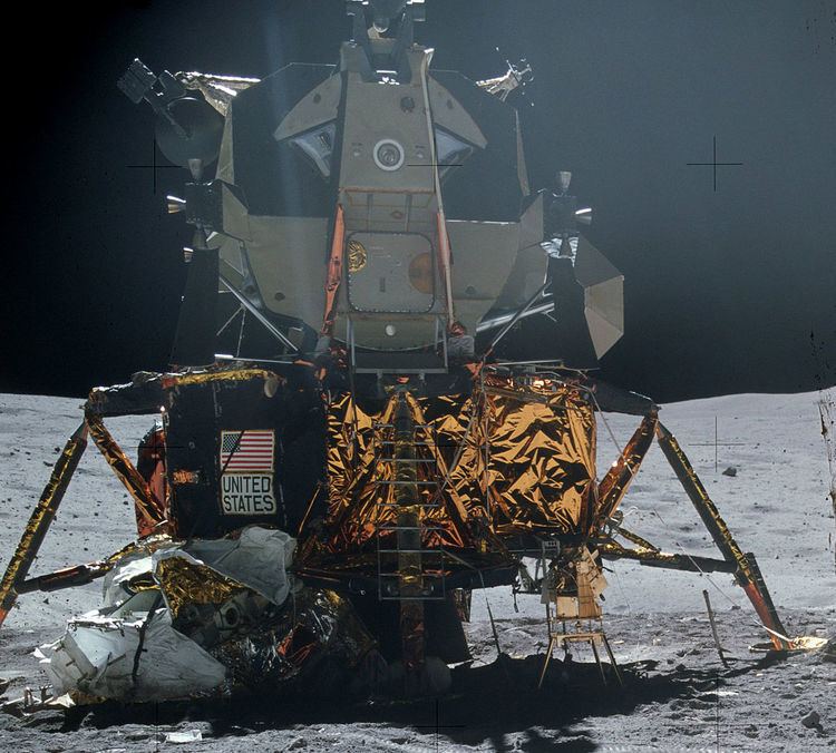
The Descent stage's primary job was to support a powered landing and surface extravehicular activity. When the excursion was over, it served as the launch pad for the ascent stage. Octagon-shaped, it was supported by four folding landing gear legs, and contained a throttleable Descent Propulsion System (DPS) engine with four hypergolic propellant tanks. A continuous-wave Doppler radar antenna was mounted by the engine heat shield on the bottom surface, to send altitude and rate of descent data to the guidance system and pilot display during the landing. Almost all external surfaces, except for the top, platform, ladder, descent engine and heat shield, were covered in amber, dark (reddish) amber, black, silver, and yellow aluminized Kapton foil blankets for thermal insulation. The number 1 (front) landing leg had an attached platform (informally known as the "porch") in front of the ascent stage's EVA hatch and a ladder, which the astronauts used to ascend and descend between the cabin to the surface. The footpad of each landing gear contained a 67-inch (170 cm)-long surface contact sensor probe, which signaled the commander to switch off the descent engine. (The probe was omitted from the number 1 leg of every landing mission, to avoid a suit-puncture hazard to the astronauts, as the probes tended to break off and protrude upwards from the surface.)
Equipment for the lunar exploration was carried in the Modular Equipment Stowage Assembly (MESA), a drawer mounted on a hinged panel dropping out of the lefthand forward compartment. Besides the astronaut's surface excavation tools and sample collection boxes, the MESA contained a television camera with a tripod; as the commander opened the MESA by pulling on a lanyard while descending the ladder, the camera was automatically activated to send the first pictures of the astronauts on the surface back to Earth. A United States flag for the astronauts to erect on the surface was carried in a container mounted on the ladder of each landing mission.
The Early Apollo Surface Experiment Package (EASEP) (later the Apollo Lunar Surface Experiment Package (ALSEP)), was carried in the opposite compartment behind the LM. An external compartment on the right front panel carried a deployable S-band antenna which, when opened looked like an inverted umbrella on a tripod. This was not used on the first landing due to time constraints, and the fact that acceptable communications were being received using the LM's S-band antenna, but was used on Apollo 12 and 14. A hand-pulled Modular Equipment Transporter (MET), similar in appearance to a golf cart, was carried on Apollo 13 and 14 to facilitate carrying the tools and samples on extended moonwalks. On the extended missions (Apollo 15 and later), the antenna and TV camera were mounted on the Lunar Roving Vehicle, which was carried folded up and mounted on an external panel. Compartments also contained replacement Portable Life Support System (PLSS) batteries and extra lithium hydroxide canisters on the extended missions.
Apollo Telescope Mount
One proposed Apollo Application was an orbital solar telescope constructed from a surplus LM with its descent engine replaced with a telescope controlled from the ascent stage cabin, the landing legs removed and four "windmill" solar panels extending from the descent stage quadrants. This would have been launched on an unmanned Saturn 1B, and docked with a manned Command/Service Module, named the Apollo Telescope Mission (ATM).
This idea was later transferred to the original wet workshop design for the Skylab orbital workshop and renamed the Apollo Telescope Mount to be docked on a side port of the workshop's Multiple Docking Adapter (MDA). When Skylab changed to a "dry workshop" design pre-fabricated on the ground and launched on a Saturn V, the telescope was mounted on a hinged arm and controlled from inside the MDA. Only the octagonal shape of the telescope container, solar panels and the Apollo Telescope Mount name were kept, though there was no longer any association with the LM.
LM Truck
The Apollo LM Truck (also known as Lunar Payload Module) was a stand-alone LM descent stage intended to deliver up to 11,000 pounds (5.0 t) of payload to the Moon for an unmanned landing. This technique was intended to deliver equipment and supplies to a permanent manned lunar base. As originally proposed, it would be launched on a Saturn V with a full Apollo crew to accompany it to lunar orbit and guide it to a landing next to the base; then the base crew would unload the "truck" while the orbiting crew returned to Earth. In later AAP plans, the LPM would have been delivered by an unmanned lunar ferry vehicle.
Depiction in film and television
During the third season of the Irwin Allen TV show Lost in Space, a copy of the LM called the "Pod" was used for short exploratory missions away from the Jupiter 2 spacecraft. Though appearing realistic on the low graphic television of the day, it was actually constructed out of plywood.
The Ron Howard film Apollo 13, a dramatization of that mission starring Tom Hanks, Kevin Bacon, and Bill Paxton, was filmed using realistic spacecraft interior reconstructions of the Aquarius and the Command Module Odyssey.
The development and construction of the lunar module is dramatized in the miniseries From the Earth to the Moon episode entitled "Spider". This is in reference to LM-3, used on Apollo 9, which the crew named Spider after its spidery appearance. The unused LM-13 stood in during the teleplay to depict LM-3 and LM-5, Eagle, used by Apollo 11.