
 | ||
Amtrak's 25 Hz traction power system is a traction power grid operated by Amtrak along the southern portion of its Northeast Corridor (NEC): the 225 route miles (362 km) between Washington, D.C. and New York City and the 104 route miles (167 km) between Philadelphia and Harrisburg, Pennsylvania. The Pennsylvania Railroad constructed it between 1915 and 1938. Amtrak inherited the system from Penn Central, the successor to Pennsylvania Railroad, in 1976 along with the Northeast Corridor. This is the reason for using 25 Hz, as opposed to 60 Hz - which is the standard for power transmission in North America. In addition to serving the NEC, the system provides power to New Jersey Transit Rail Operations (NJT), the Southeastern Pennsylvania Transportation Authority (SEPTA) and the Maryland Area Regional Commuter Train (MARC). Only about half of the system's electrical capacity is used by Amtrak. The remainder is sold to the commuter railroads who operate their trains along the corridor.
Contents
- History
- Specifications and statistics
- Former converter and power stations
- Declining need for 25Hz power
- Long Island City Generating Station
- Waterside Generating Station
- Benning Frequency Changer
- Radnor synchronous condenser
- Substations
- Transmission lines
- Recent developments
- Ivy City substation project
- Conestoga to Atglen transmission line
- Zoo to Paoli transmission line
- Hamilton substation project
- Morton and Lenni
- Lenni
- Morton
- Recent problems
- May 26 2006 Blackout
- December 23 2009 Brownout
- August 24 2010 Brownout
- OctoberNovember 2012 Hurricane Sandy
- References
History
The Pennsylvania Railroad (PRR) began experimenting with electric traction in 1910, coincident with their completion of the trans-Hudson tunnels and New York Penn Station. These initial systems were low-voltage direct current (DC) third rail systems. While they performed adequately for tunnel service, the PRR ultimately determined them to be inadequate for long distance, high-speed electrification.
Other railroads had by this time experimented with low frequency (less than 60 Hz) alternating current (AC) systems. These low-frequency systems had the AC advantage of higher transmission voltages, reducing resistive losses over long distances, as well as the typically DC advantage of easy motor control as universal motors could be employed with transformer tap changer control gear. Pantograph contact with trolley wire is also more tolerant of high speeds and variations in track geometry. The New York, New Haven and Hartford Railroad had already electrified a portion of its Main Line in 1908 at 11 kV AC 25 Hz and this served as a template for the PRR, which installed its own trial main line electrification between Philadelphia and Paoli, Pennsylvania in 1915. Power was transmitted along the tops of the catenary supports using four single phase, 2 wire 44 kV distribution circuits. Tests on the line using experimental electric locomotives such as the PRR FF1 revealed that the 44 kV distribution lines would be insufficient for heavier loads over longer distances.
In the 1920s the PRR decided to electrify major portions of its eastern rail network and because any sort of commercial electric grid simply did not yet exist at the time the railroad constructed its own distribution system to transmit power from a select number of generating sites to trains possibly hundreds of miles distant. To accomplish this the PRR chose to implement a pioneering system of single-phase high voltage transmission lines at 132 kV, stepped down to the 11 kV at regularly spaced substations along the right of way.
The first line to be electrified under this new system was between Philadelphia and Wilmington, Delaware in the late 1920s. By 1930, catenary extended from Philadelphia to Trenton, New Jersey, by 1933 to New York City, and by 1935 south to Washington, D.C. Finally in 1939 the main line from Paoli west to Harrisburg was completed along with several freight-only lines. Also included were the Trenton Cutoff and the Port Road Branch. Superimposed on these electrified lines was an independent power grid delivering 25 Hz current from the point of generation to electric locomotives anywhere on nearly 500 route miles (800 km) of track, all under the control of electric power dispatchers in Harrisburg, Baltimore, Philadelphia and New York City.
Northeast railroads atrophied in the years following World War II; the PRR was no exception. The infrastructure of the northeast corridor remained essentially unchanged through the series of mergers and bankruptcies which ended in Amtrak's creation and acquisition of the former PRR lines which came to be known as the Northeast Corridor. The circa 1976 Northeast Corridor Improvement Project had originally planned to convert the PRR's system to the utility grid standard of 60 Hz. Ultimately, this plan was shelved as economically infeasible and the electrical traction infrastructure was left largely unchanged with the exception of a general traction power voltage increase to 12 kV and a corresponding transmission voltage increase to 138 kV.
During the 1970s, several of the original converter or power stations which had originally supplied power to the system were shut down. Also the end of electrified through-freight service on the Main Line to Paoli allowed the original 1915 substations and their 44 kV distribution lines to be decommissioned with that 20-mile (32 km) section of track being fed from 1930s-era substations on either end. In the decade between 1992 and 2002, several static converter stations were commissioned to replace stations that had or were being shut down. Jericho Park, Richmond, and Sunnyside Yard converters were all installed during this period. This replaced much of the electrical frequency conversion equipment, but the lineside transmission and distribution equipment were unchanged.
In 2003, Amtrak commenced a capital improvement plan that involved planned replacement of much of the lineside network including 138/12 kV transformers, circuit breakers, and catenary wire. Statistically, this capital improvement has resulted in significantly fewer delays, although dramatic system shutdowns have still occurred.
Specifications and statistics
The 25 Hz system was built by the Pennsylvania Railroad with a nominal voltage of 11.0 kV. The nominal operating voltages were raised in 1948 and are now:
As of 1997, the system included:
Over 550 GWh of energy are consumed annually by locomotives on the system. If this was consumed at a constant rate over the entire year (although it is not in practice), the average system load would be approximately 63 MW.
The system power factor varies between 0.75 and around 0.85.
Former converter and power stations
The majority of power sources in the original Pennsylvania Railroad electrification were built prior to 1940. Some have been retired out-right, others have been replaced with co-located static frequency converters, and others remain in service and will be refurbished and operated indefinitely. The following tables lists sources which are no longer in service.
Declining need for 25 Hz power
During the beginning of the 20th century, 25 Hz power was much more readily available from commercial electrical utilities. The vast majority of urban subway systems used 25 Hz power to supply their lineside rotary converters used to generate the DC voltage supplied to the trains. Since rotary converters work more efficiently with lower frequency supplies, 25 Hz was a common supply frequency for these machines. Rotary converters have been steadily replaced over the past 70 years with, at first, mercury arc rectifiers and more lately solid-state rectifiers. Thus, the need for special frequency power for urban traction has disappeared, along with the financial motivation for utilities to operate generators at these frequencies.
Long Island City Generating Station
Long Island City Power Station in Hunter's Point, NY was built by the Pennsylvania Railroad in 1906 in preparation for the North River Tunnels and the opening of Pennsylvania Station in Manhattan. The station consisted of 64 coal-fired boilers and three steam turbine generators with a total capacity of 16 MW. In 1910, the station was expanded with two additional turbine generators for a total capacity of 32.5 MW. Power was transmitted to rotary converters (AC to DC machines) for use in the PRR's original third rail electrification scheme. Like most DC electric distribution systems of the time (Thomas Edison's being the most famous), 25 Hz power was used to drive rotary converters at substations along the line. Some sources state that the station was largely dormant by the 1920s. When AC overhead electrification was extended in the 1930s, Long Island City connected to the 11 kV catenary distribution system. Operation of the station was transferred to Consolidated Edison in 1938, although ConEd began supplying power from the adjacent Waterside Generating Station, most likely due to declining overall demand for 25 Hz power. The station was disused and sold in the mid-1950s. 40.7430°N 73.9581°W / 40.7430; -73.9581 (Long Island City Generating Station (Disused))
Waterside Generating Station
Originally constructed by Consolidated Edison to supply power to their DC distribution system in Manhattan, Waterside began supplying power to the PRR's AC system around 1938 when ConEd assumed operation of the Long Island City Station. The single-phase turbine generators were retired in the mid-1970s due to safety concerns. Two transformers were installed to supply catenary power from remaining (three-phase) portions of ConEd's still relatively extensive 25 Hz system. Power flow management problems prevented usage of this source under other than emergency conditions. 40.7464°N 73.9707°W / 40.7464; -73.9707 (Waterside Generating Station (Demolished))
Benning Frequency Changer
In 1986, Baltimore Gas and Electric elected to not renew the contract under which it had operated the Benning Power Station frequency changer on behalf of Amtrak. They proposed a static frequency changer which was built at Jericho Park (Bowie, Maryland) and placed on service in the spring of 1992. 38.897534°N 76.959298°W / 38.897534; -76.959298 (Benning Frequency Changer ( demolished))
Radnor synchronous condenser
Although reactive power has primarily been supplied along with real power by the steam turbines and motor generators of the system, the PRR briefly used two synchronous condensers. Shortly after commissioning the 1915 electrification, the railroad discovered that the 44 kV feeders and large inductive loads on the system were causing significant voltage sag. The supplying electric utility (Philadelphia Electric) also discovered that power factor correction was needed. In 1917, the PRR installed two 11 kV, 4.5 MVA synchronous converters at Radnor, the approximate center point of the system load. This substation was located at the site of water tanks used to supply water to track pans which supplied water to conventional locomotives. At some later time, the converters were shut down and removed. Dedicated machines for reactive power support have not been used subsequently by either the PRR or Amtrak. 40.044725°N 75.359463°W / 40.044725; -75.359463 (Radnor)
Substations
The PRR's original 1915 electrification made use of four substations, at Arsenal Bridge, West Philadelphia, Bryn Mawr, and Paoli. The Arsenal Bridge substation stepped-up 13.2 kV, 25 Hz power supplied from PECO's Schuylkill power station on Christian Street to 44 kV for distribution. The remaining three substations reduced the 44 kV distribution voltage to 11 kV trolley voltage. The substations were operated from adjacent signal towers. They used typical period concrete buildings to house the transformers and switchgear while the line terminals were on the roof. From 1918 onwards outdoor stations were used and when the main line electrification began in 1928 the stations became large open air structures using lattice steel frameworks to mount the 132 kV terminations and switchgear. By 1935 new stations were connected to remote supervision systems allowing power directors to open and close switches and breakers from central offices without having to go through the tower operators.
Today about 55 substations are part of Amtrak's network. Substations are spaced on average 8 miles apart and feed 12 kV catenary circuits in both directions along the line. Thus the catenary is segmented (via section breaks, also called 'sectionalizations' by the PRR) at each substation, and each substation feeds both sides of a catenary's section break. A train traveling between two substations draws power through both transformers.
A typical substation includes two to four 138/12 kV transformers, 138 kV air switches that permit isolation of individual transformers, shutdown one of the two 138 kV feeders, or cross-connection from one feeder to another. The output of the transformers is routed to track catenary via 12 kV circuit breakers and air disconnect switches. Cross-connect switches allow one transformer to feed all catenary lines.
The PRR substation architecture was based on a long distance, high speed railway. The substation spacing ensures that any train is never more than 4 or 5 miles from the nearest substation, which minimized voltage drop. One disadvantage to the substation design as originally built by the PRR concerns its lack of 138 kV circuit breakers. Essentially all segmentation of the 138 kV system must be done by hand. This makes rapid isolation of a fault on the 138 kV line very slow. Faults in one part of the line also affect the entire distribution system since it is impossible for the 138 kV transmission to protect or reconfigure itself during a fault condition. High voltage faults generally are cleared by opening converter output breakers, which causes a concurrent loss of the converter. The system does not degrade gracefully under high voltage faults. Rather than isolating, for example, the south 138 kV feeder between Washington and Perryville, the system would require opening converter output breakers at Jericho Park and Safe Harbor. This results in loss of much more of the network than is required to simply isolate the fault.
Transmission lines
All transmission lines within the 25 Hz system are two-wire, single-phase, 138 kV. The center tap of each 138 kV/12 kV transformer is connected to ground, thus the two transmission lines are tied to ±69 kV with respect to ground and 138 kV relative to each other.
Generally two separate two-wire circuits travel along the rail line between substations. One circuit is mounted at the top of the catenary poles on one side of the track; the second circuit runs along the other side.
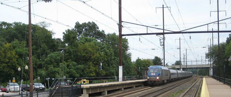
The arrangement of catenary supports and transmission wires gives the overhead structure along former Pennsylvania Railroad lines its characteristic 80-foot (24 m)-tall 'H'-shaped structure. They are much taller than the overhead electrification structures on other electrified American railroads due to the 138 kV transmission lines. Catenary towers and transmission lines along former New York, New Haven and Hartford Railroad lines and Amtrak's New England division are much shorter, and are recognizable due to different design and construction.
While a majority of the transmission infrastructure is located directly above the rail lines on the same structure that supports the catenary system, some lines are either located above lines that have been de-electrified or abandoned or in a few cases on completely independent rights of way.
The following is a list of all major segments of the 25 Hz 138 kV transmission infrastructure listing substations (SS or Sub) or high-tension switching stations (HT Sw'g) as termini. For clarity, positions of substations are not repeated in this table. A listing of the high-tension switching stations follows.
Recent developments
Amtrak's capital improvement program which began in 2003 has continued to the present day and has since 2009, received added support from economic stimulus funding sources (American Recovery and Reinvestment Act of 2009 or ARRA).
Major improvements in 2010 included:
Major improvements planned for the future include:
Ivy City substation project
The Ivy City substation project marked the first extension of 138 kV transmission line since Safe Harbor Dam was constructed in 1938. In the original PRR electrification scheme, the 138 kV transmission lines went south from Landover to the Capital South substation rather than following the line through Ivy City to the northern approach to Union Station. The two tracks between Landover and Union Station had no high voltage transmission line above them; Union Station catenary was fed at 12 kV from the Landover and Capitol substations (the latter via the First Street Tunnels). When the Capitol South substation was abandoned, coincident with the de-electrification of the track between Landover and Potomac Yard, Union Station and its approaches became a single-end fed section of track. This combined with rising traffic levels resulted in low voltage conditions on the approaches to Union Station and decreased system reliability.
The Ivy City project resulted in the installation of two 4.5 MVA transformers in a 138/12 kV substation on the northeast edge of the Ivy City yard complex and 5.2 miles (8.4 km) of 138 kV transmission line to augment the overstretched facilities at Landover. Since the original catenary supports along this section of track were only high enough for the 12 kV catenary wire, the 138 kV lines were installed on new steel monopod poles installed along the right-of-way. Except for the fact that the new poles only carry four conductors rather than the typical six for a utility line, the new line appears as a typical medium voltage power line rather than the typical PRR style H-shaped structure.
Conestoga to Atglen transmission line
In 2011, Amtrak replaced the transmission lines that tie the Conestoga Substation to Parkesburg via Atglen. These lines were originally installed over the Atglen and Susquehanna Branch. The line was subsequently abandoned by Conrail and the tracks removed, but Amtrak has retained an easement to operate its 138 kV transmission lines over the roadbed. Towers and conductors and wire over 24 miles (39 km) of the route were replaced; work was completed in September 2011. The scope of work included:
Funding for this project was included under the ARRA program. The specified number of poles, spaced approximately 500 feet (150 m) per tower, is approximately twice as far apart as the span length between the 1930s structures, which averaged 270 feet (82 m).
Zoo to Paoli transmission line
In late 2010, Amtrak solicited design services for new transmission lines between Paoli and Zoo substations. Primary objectives of this expansion include improving reliability of transmission between Safe Harbor and Philadelphia, and reducing maintenance costs. This project complements the Safe Harbor to Atglen transmission line replacement, which has already been completed.
The Zoo to Paoli transmission line would replace the current supply scheme which uses 138 kV lines which run circuitously along the SEPTA Cynwyd Line, the Schuylkill Branch rail-trails and the Trenton Cut-off between the Zoo and Frazer substations. The new routing will reduce maintenance costs, as Amtrak must maintain transmission poles and control vegetation along right-of-way which it neither owns nor uses for revenue service. The conceptual line will run from the existing Paoli substation to the junction of the Harrisburg to Philadelphia main line and SEPTA's Cynwyd Line at 52nd Street in West Philadelphia. 39.9785°N 75.2280°W / 39.9785; -75.2280 (End of New Construction for Paoli-Zoo Transmission Lines).
The new lines would connect to the existing 1ED and 2ED circuits, which would be abandoned between the junction and their current terminus at the Earnest Junction HT Switch. The plan also includes construction of a 138/12 kV substation at Bryn Mawr to replace the existing switching station. The existing 1915 catenary structures are planned for replacement, and new transmission supports will be compatible with catenary replacement.
Hamilton substation project
A new substation (Number 34A) called Hamilton was constructed in Mercer County, NJ. Work on the site began in early 2013, and the substation sap put into service in early 2015.
Morton and Lenni
The Morton #01 and Lenni #02 substations are owned by SEPTA and supply the Media/Elwyn Line; therefore, they are not covered by Amtrak capital funding programs. SEPTA's own capital improvement plan, formulated in late 2013 after passage of funding legislation in Pennsylvania, allowed for the renewal of all components at Morton and Lenni.
Lenni
In October 2014 SEPTA requested interested contractors to submit bids for the rehabilitation of Lenni substation. In December 2014 SEPTA awarded a $6.82 million contract to Vanalt Electrical for the work. The work was completed by the end of fall 2016.
Morton
In February 2014 SEPTA awarded a $6.62 million contract to Philips Brothers Electrical Contractors Inc. for the rehabilitation of Morton substation. The work was completed by the end of fall 2016.
Recent problems
Despite the recent capital improvements throughout the system, several high-profile power failures have occurred along the NEC in recent years.
May 26, 2006 Blackout
On May 25, 2006, during restoration from maintenance on one of the Richmond inverter modules, a command to restore the module to full output capability was not executed. The system tolerated this reduced capacity for about 36 hours, during which time the problem went unnoticed. During rush hour the next morning (May 26), the overall capacity became overloaded:
By 8:03 am, the entire 25 Hz system, stretching from Washington, D.C. to Queens, New York, was shut down. About 52,000 people were stranded on trains or otherwise affected. Two New Jersey Transit trains stranded under the Hudson River were retrieved by diesel locomotives. Restoration was hampered by policies which allowed the converter stations to operate unattended during rush hour periods. The 25 Hz system was restored by a 'black start' using the Safe Harbor water turbines, and most service along the system returned to normal by mid-afternoon. Amtrak subsequently improved its system of maintaining 'rescue' diesel locomotives near the Hudson River tunnels.
December 23, 2009 Brownout
Low system voltage around New York City caused a halt of trains in and around the New York area at 8:45 am on Wednesday, December 23, 2009. Power was never fully lost, and full voltage was restored by 11:30 am. Amtrak stated that an electrical problem in North Bergen, New Jersey (near the western portal and the Union City substation) caused the problem, but did not further elaborate on the nature of the malfunction.
August 24, 2010 Brownout
Low system voltages beginning at 7:45 am on Tuesday, August 24, 2010, caused Amtrak to order an essentially system-wide stoppage of trains within the 25 Hz traction network. Slow-speed service was gradually restored, and the power problem was corrected by 9:00 am, although delays persisted the remainder of the morning.
October–November 2012: Hurricane Sandy
On October 29, 2012, Hurricane Sandy struck the northeast coast of the U.S. Augmented by a nor'easter, the storm surge from Sandy raced through the Hackensack Meadows, severely damaging (among other railroad infrastructure) Kearney Substation #41 and knocking it offline. This loss of electrical capacity forced Amtrak and New Jersey Transit to operate fewer trains, using modified weekend schedules. With assistance from the U.S. Army Corps of Engineers, the substation was isolated from floodwaters and then dewatered. After testing the substation's components, the degree of damage was determined to be less than initially feared, and after further repairs, Kearney Substation came back on-line on Friday, November 16, allowing the immediate return of all Amtrak and gradual return of all NJ Transit electric trains into Penn Station through the dewatered North River Tunnels.
Amtrak has since requested federal funding to upgrade Kearny substation so it is high enough to not be affected by flood water.