
 | ||
Single-phase generator (also known as single-phase alternator) is an alternating current electrical generator that produces a single, continuously alternating voltage. Single-phase generators can be used to generate power in single-phase electric power systems. However, polyphase generators are generally used to deliver power in three-phase distribution system and the current is converted to single-phase near the single-phase loads instead. Therefore, single-phase generators are found in applications that are most often used when the loads being driven are relatively light, and not connected to a three-phase distribution, for instance, portable engine-generators. Larger single-phase generators are also used in special applications such as single-phase traction power for railway electrification systems.
Contents
Revolving armature
The design of revolving armature generators is to have the armature part on a rotor and the magnetic field part on stator. A basic design, called elementary generator, is to have a rectangular loop armature to cut the lines of force between the north and south poles. By cutting lines of force through rotation, it produces electric current. The current is sent out of the generator unit through two sets of slip rings and brushes, one of which is used for each end of the armature. In this two-pole design, as the armature rotates one revolution, it generates one cycle of single phase alternating current (AC). To generate an AC output, the armature is rotated at a constant speed having the number of rotations per second to match the desired frequency (in hertz) of the AC output.
The relationship of armature rotation and the AC output can be seen in this series of pictures. Due to the circular motion of the armature against the straight lines of force, a variable number of lines of force will be cut even at a constant speed of the motion. At zero degrees, the rectangular arm of the armature does not cut any lines of force, giving zero voltage output. As the armature arm rotates at a constant speed toward the 90° position, more lines are cut. The lines of force are cut at most when the armature is at the 90° position, giving out the most current on one direction. As it turns toward the 180° position, lesser number of lines of force are cut, giving out lesser voltage until it becomes zero again at the 180° position. The voltage starts to increase again as the armature heads to the opposite pole at the 270° position. Toward this position, the current is generated on the opposite direction, giving out the maximum voltage on the opposite side. The voltage decrease again as it completes the full rotation. In one rotation, the AC output is produced with one complete cycle as represented in the sine wave.
More poles can also be added to single-phase generator to allow one rotation to produce more than one cycle of AC output. In an example on the left, the stator part is reconfigured to have 4 poles which are equally spaced. A north pole is adjacent to the two south poles. The shape of the armature at the rotor part is also changed. It is no longer a flat rectangle. The arm is bent 90 degrees. This allows one side of the armature to interact with a north pole while the other side interacts with a south pole similarly to the two-pole configuration. The current is still delivered out through the two sets of slip rings and brushes in the same fashion as in the two-pole configuration. The difference is that a cycle of AC output can be completed after a 180 degree rotation of the armature. In one rotation, the AC output will be two cycles. This increases the frequency of the output of the generator. More poles can be added to achieves higher frequency at the same rotation speed of the generator, or same frequency of output at the lower rotation speed of the generator depending on the applications.
This design also allows us to increase the output voltage by modifying the shape of the armature. We can add more rectangular loops to the armature as seen on the picture on the right. The additional loops at the armature arm are connected in series, which are actually additional windings of the same conductor wire to form a coil in rectangular shape. In this example, there are 4 windings in the coil. Since the shapes of all windings are the same, the amount of the lines of force will be cut at the same amount in the same direction at the same time in all windings. This creates in phase AC output for these 4 windings. As a result, the output voltage is increased 4 time as shown in the sine wave in the diagram.
Revolving field
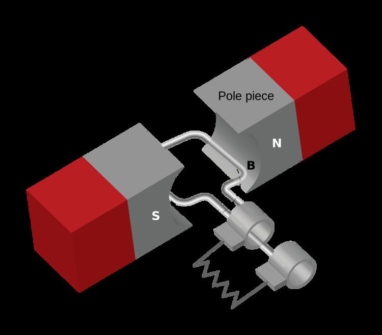
The design of revolving field generators is to have the armature part on stator and the magnetic field part on rotor. A basic design of revolving field single-phase generator is shown on the right. There are two magnetic poles, north and south, attached to a rotor and two coils which are connected in series and equally spaced on stator. The windings of the two coils are in reverse direction to have the current to flow in the same direction because the two coils always interact with opposing polarities. Since poles and coils are equally spaced and the locations of the poles match to the locations of the coils, the magnetic lines of force are cut at the same amount at any degree of the rotor. As a result, the voltages induced to all windings have the same value at any given time. The voltages from both coils are "in phase" to each other. Therefore the total output voltage is two times the voltage induced in each winding. In the figure, at the position where pole number 1 and coil number 1 meet, the generator produces the highest output voltage on one direction. As the rotor turns 180 degrees, the output voltage is alternated to produce the highest voltage on the other direction. The frequency of the AC output in this case equals to the number of rotations of the rotor per second.
This design can also allow us to increase the output frequency by adding more poles. In this example on the right, we have 4 coils connected in series on the stator and the field rotor has 4 poles. Both coils and poles are equally spaced. Each pole has opposite polarity to its neighbors which are angled at 90 degrees. Each coils also have opposite winding to its neighbors. This configuration allows the lines of force at 4 poles to be cut by 4 coils at the same amount at a given time. At each 90-degree rotation, the voltage output polarity is switched from one direction to the other. Therefore, there are 4 cycles of the AC output in one rotation. As the 4 coils are wired in series and their outputs are "in phase", the AC output of this single-phase generator will have 4 times the voltage of that generated by each individual coil.
A benefit of the revolving field design is that if the poles are permanent magnets, then there is no need to use any slip ring and brush to deliver electricity out of the generator as the coils are stationary and can be wired directly from the generator to the external loads.
Small generators
Single-phase generators that people are familiar with are usually small. The applications are for standby generators in case of main power supply is interrupted and for supplying temporary power on construction sites.
Another application is in small wind technology. Although most of wind turbines use three-phase generators, single-phase generators are found in some of the small wind turbine models with rated power outputs of up with 55 kW. The single-phase models are available in the vertical axis wind turbines (VAWT) and Horizontal-axis wind turbines (HAWT).
Power stations
In the very early days of electricity generation, the generators at power stations had been single-phase AC or direct current. The direction of the power industry were changing in 1895 when more efficient polyphase generators were successfully implemented at Adams Hydroelectric Generating Plant which was the first large-scale polyphase power station. Newer power stations started to adopt the polyphase system. In the 1900s, many railways started the electrification of their lines. During that time, the single-phase AC system had been widely used for their traction power networks beside the direct current system. The early generators for those single-phase traction networks are single-phase generators. Even with newer three-phase motors which were introduced to some modern trains, the single-phases transmission for traction networks survive their time and are still in use in many railways today. However, many traction power stations have replaced their generators over time to use three-phase generators and convert into single-phase for transmission.
Hydro
In the early development of hydroelectricity, single-phase generators played an important role in demonstrating the benefits of alternating current. In 1891, a 3,000 volts and 133 Hz single-phase generator of 100 horsepower was installed at Ames Hydroelectric Generating Plant which was belt-connected with Pelton water wheel. The power was transmitted through 4.2 kilometres (2.6 mi) cables to power an identical motor at the mill. The plant was the first to generate alternating current electric power for industrial application and it was a demonstration of the efficiency in AC transmission. This was a precedent to larger for much larger plants such as the Edward Dean Adams Power Plant in Niagara Falls, New York in 1895. However, the larger plants were operated using polyphase generators for greater efficiency. That left the applications for single-phase hydroelectricity generation to special cases such as in light loads.
An example of using single-phase in a special case was implemented in 1902 at St. Louis Municipal Electric Power Plant. A 20 kW single-phase generator was direct-connected to a Pelton water wheel to generate electricity enough to power light loads. This was an early demonstration of in-conduit hydro to capture energy from water flow in the public water pipeline. The energy for the water main in this case was not created by gravity, but the water was pumped by a larger steam engine at a water pumping station to supply water to customers. The decision to have water pumped by a larger engine then take some of the energy from water flow to power a smaller generator using water wheel was based on the cost. At the time, steam engines were not efficient and cost effective for a 20 kW system. Therefore, they installed a steam water pump to have enough energy to maintain water pressure for customer and to drive a small generator at the same time.
The main usage of single-phase hydroelectricity generation today is to supply power for traction network for railways. Many electrical transmission networks for railways especially in Germany rely on single-phase generation and transmission which are still in use today. A notable power station is Walchensee Hydroelectric Power Station in Bavaria. The station takes water from elevated Lake Walchensee to drive eight turbines that drive the generators. Four of those are three-phase generators to supply the power grid. The other four are single-phase generators are connected to Pelton turbines which have combined capacity of 52 MW to supply the German 15 kV AC railway electrification.
Similar single-phase hydroelectricity generations are also used in another variance of railway electrification system in the United States. A power station at Safe Harbor Dam in Pennsylvania provides power generation for both public utilities and for Amtrak railway. Two out of its 14 turbines are connected to two single-phase generators to supply Amtrak's 25 Hz traction power system. The two turbines are of Kaplan type with 5 blades rated 42,500 horsepower.
Steam
In the early years, steam engines were used as prime movers of generators. An installation at St. Louis Municipal Electric Power Plant in the 1900s was an example of using steam engines with single-phase generators. The St. Louis plant used compound steam engine to drive a 100 kW single-phase generator which produced current at rated power of 1,150 volts.
The steam engines were also used during the twentieth century in power stations for traction networks which had single-phase power distribution for specific railways. A special set of single-phase generators with steam turbines at Waterside Generating Station in New York City in 1938 was an example of such generation and distribution systems. The single-phase generators were eventually retired in the late 1970s due to concerns of a turbine failure in another station. The generators were replaced by two transformers to reduce from another three-phase power source to existing single-phase catenary power. Eventually, the transformers were replaced by two solid-state cycloconverter instead.
Nuclear
Normally, nuclear power plants are used as base load stations with very high capacities to supply power to the grids. Neckarwestheim I in Neckarwestheim is a unique nuclear power plant in that it is equipped with high-capacity single-phase generators to supply Deutsche Bahn railway with specific AC voltage at frequency of 16 2/3 Hz. The pressurized water reactor transport thermal energy to two turbines and generators which are rated for 187 MW and 152 MW.