
 | ||
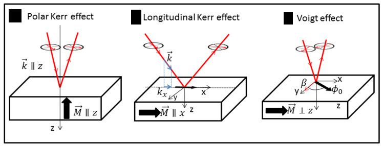
The Voigt effect is a magneto-optical phenomenon which rotates and elliptizes linearly polarised light sent into an optically active medium. Unlike many other magneto-optical effects such as the Kerr or Faraday effect which are linearly proportional to the magnetization (or to the applied magnetic field for a non magnetized material), the Voigt effect is proportional to the square of the magnetization (or square of the magnetic field) and can be seen experimentally at normal incidence. There are several denominations for this effect in the literature: the Cotton–Mouton effect (in reference to French scientists Aimé Cotton and Henri Mouton), the Voigt effect (in reference to the German scientist Woldemar Voigt), and magnetic-linear birefringence This last denomination is closer in the physical sense, where the Voigt effect is a magnetic birefringence of the material with an index of refraction parallel (
Contents
- Theory
- Dielectric tensor
- Eigenvalues and eigenvectors
- Continuity relation
- Calculation of rotation angle
- Transmission geometry
- Illustration of Voigt effect in GaMnAs
- References
For an electromagnetic incident wave linearly polarized
and in the transmission geometry :
where
Detailed calculation and an illustration are given in sections below.
Theory
As with the other magneto-optical effects, the theory is developed in a standard way with the use of an effective dielectric tensor from which one calculates systems eigenvalues and eigenvectors. As usual, from this tensor, magneto-optical phenomena are described mainly by the off-diagonal elements.
Here, one considers an incident polarisation propagating in the z direction:
Dielectric tensor
Following the notation of Hubert, the generalized dielectric cubic tensor
where
Eigenvalues and eigenvectors
To calculate the eigenvalues and eigenvectors, we consider the propagation equation derived from the Maxwell equations, with the convention
When the magnetization is perpendicular to the propagation wavevector, on the contrary to the Kerr effect,
Eigenvalues and eigenvectors are found by solving the propagation equation on
The corresponding eigenvectors for
Continuity relation
Knowing the eigenvectors and eigenvalues inside the material, one have to calculate
The solution of this system of equation are :
Calculation of rotation angle
The rotation angle
where
Transmission geometry
The calculation of the rotation of the Voigt effect in transmission is in principle equivalent to the one of the Faraday effect. In practice, this configuration is not used in general for ferromagnetic samples since the absorption length is weak in this kind of material. However, the use of transmission geometry is more common for paramagnetic liquid or cristal where the light can travel easily inside the material.
The calculation for a paramagnetic material is exactly the same with respect to a ferromagnetic one, except that the magnetization is replace by a field
Consider the transmitted electromagnetic waves
Again we obtain something proportional to
Illustration of Voigt effect in GaMnAs
As an illustration of the application of the Voigt effect, we give an example in the magnetic semiconductor (Ga,Mn)As where a large Voigt effect was observed. At low temperatures (in general for
A typical hysteresis cycle containing the Voigt effect is shown in figure 1. This cycle was obtained by sending a linearly polarized light along the [110] direction with an incident angle of approximately 3° (more details can be found in ), and measuring the rotation due to magneto-optical effects of the reflected light beam. In contrast to the common longitudinal/polar Kerr effect, the hysteresis cycle is even with respect to the magnetization, which is a signature of the Voigt effect. This cycle was obtained with a light incidence very close to normal, and it also exhibits a small odd part; a correct treatment has to be carried out in order to extract the symmetric part of the hysteresis corresponding to the Voigt effect, and the asymmetric part corresponding to the longitudinal Kerr effect.
In the case of the hysteresis presented here, the field was applied along the [1-10] direction. The switching mechanism is as follow :
- We start with a high negative field and the magnetization is close to the [-1-10] direction at position 1.
- The magnetic field is decreasing leading to a coherent magnetization rotation from 1 to 2
- At positive field, the magnetization switch brutally from 2 to 3 by nucleation and propagation of magnetic domains giving a first coercive field named here
H 1 - The magnetization stay close to the state 3 while rotating coherently to the state 4, closer from the applied field direction.
- Again the magnetization switches abruptly from 4 to 5 by nucleation and propagation of magnetic domains. This switching is due to the fact that the final equilibrium position is closer from the state 5 with respect to the state 4 (and so his magnetic energy is lower). This gives another coercive field named
H 2 - Finally the magnetization rotates coherently from the state 5 to the state 6.
The simulation of this scenario is given in the figure 2, with