
 | ||
A volume unit (VU) meter or standard volume indicator (SVI) is a device displaying a representation of the signal level in audio equipment. The Acoustical Society of America standardized it in 1942 (ANSI C16.5-1942) for use in telephone installation and radio broadcast stations. Consumer audio equipment often features VU meters, both for utilitarian purposes (e.g. in recording equipment) and for aesthetics (in playback devices).
Contents
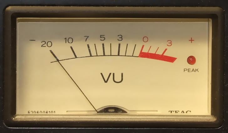
The original VU meter is a passive electromechanical device, namely a 200 µA DC d'Arsonval movement ammeter fed from a full wave copper-oxide rectifier mounted within the meter case. The mass of the needle causes a relatively slow response, which in effect integrates the signal, with a rise time of 300 ms. 0 VU is equal to +4 [dBu], or 1.228 volts RMS, a power of about 2.5 milliWatts when applied across a 600 ohm load. 0 VU is often referred to as "0 dB". The meter was designed not to measure the signal, but to let users aim the signal level to a target level of 0 VU (sometimes labelled 100%), so it is not important that the device is non-linear and imprecise for low levels. In effect, the scale ranges from −20 VU to +3 VU, with −3 VU right in the middle. Purely electronic devices may emulate the response of the needle; they are VU-meters in as much as they respect the standard.
The VU-meter (intentionally) "slows" measurement, averaging out peaks and troughs of short duration, and reflects more the perceived loudness of the material than the more modern and initially more expensive PPM meters. For this reason many audio practitioners prefer it to its alternatives, though the meter indication does not reflect some of the key features of the signal, most notably its peak level, which in many cases, must not pass a defined limit.
In the broadcast industry, loudness monitoring was standardized only recently.
Lead
The original designers of the VU meter were tasked with finding a way to measure complex audio signals with a simple technology.
Since a VU meter is a mechanical device it can never reflect the instantaneous signal peaks of complex audio signals. The designers of the VU meter therefore took a different approach. They created a meter that did NOT measure peaks but simply inferred them. A real VU meter has a very specific "ballistic characteristic". This means it responds to changing audio signals at a very precise speed, rising from no signal to 99% of "0VU" when a 1 kHz sine wave tone is applied for 300 milli-seconds.
When using a VU meter, the audio system is calibrated with a sine wave tone at a "reference level" for the system. At the reference level, the VU meter shows "0" for a sine wave tone, but the engineer must know that, with music or speech, to always infer that peak levels are always between 6dB to 10dB higher than the reference level. The usefulness of the VU meter comes from the fact that for most types of audio sources the system engineer can count on these peaks being within this range and can design the audio system with confidence. Good engineering practice is to always build in a little extra "headroom" as it is called, to cover the strange conditions where an audio signal might exceed normal peak levels or the equipment operator fails to adjust the levels correctly. Typically the levels considered when designing systems using a VU meter are:
Standard characteristics
The behaviour of VU meters is defined in ANSI C16.5-1942, British Standard BS 6840, and IEC 60268-17.
Rise time
The rise time, defined as the time it takes for the needle to reach 99% of the distance to 0 VU when the VU-meter is submitted to a signal that steps from 0 to a level that reads 0 VU, is 300 ms.
The overshoot must be within 1 to 1.5%.
The fall time is the same as the rise time, 300 ms.
Frequency response
The level specification is meant at 1000 Hz. The reading should not depart from the reading at 1000 Hz by more than 0.2 dB from 35 Hz to 10 kHz or more than 0.5 dB between 25 Hz and 16 kHz.
Note that the specification mentions only sinusoid waveforms. Given the electromechanical principle of the meter, the deviation of the needle is actually approximately proportional to the average of the part of the signal with more than approximately 0.4 V instantaneously because of the two copper-oxide rectifiers always in series, which transfer function curve has a knee around 0.2 V. Signals generally do not have a sinusoidal waveform by far, even if they all fall within the VU-meter bandpass. The reading is the average of the voltage, and is not an indication of the power of the signal, which is proportional to the average of the square of the voltage, or the root-mean-square (RMS) value. As a conventional VU reading, however, it served its purpose as an indication a) of the overall level and dynamics of the signal and b) of the proximity to the maximum admitted level, to the operators of recording and broadcasting equipment. Maintenance staff could also use it as a measurement apparatus, to check for losses in transmissions and level alignment, provided that they used exclusively sine waves as test signals.
Impedance
The VU meter and its attenuator should present a 7500 ohm impedance to the circuit it is applied to, measured with a sinusoid signal that sets the indicator to 0 dB.
History
The VU-meter was originally developed in 1939 by the combined effort of Bell Labs and broadcasters CBS and NBC.
Other level meters
The consumer audio industry has produced a number of volume indicators that often do not comply with the standard.