
 | ||
A tuned radio frequency receiver (or TRF receiver) is a type of radio receiver that is composed of one or more tuned radio frequency (RF) amplifier stages followed by a detector (demodulator) circuit to extract the audio signal and usually an audio frequency amplifier. This type of receiver was popular in the 1920s. Early examples could be tedious to operate because when tuning in a station each stage had to be individually adjusted to the station's frequency, but later models had ganged tuning, the tuning mechanisms of all stages being linked together, and operated by just one control knob. By the mid 1930s, it was replaced by the superheterodyne receiver patented by Edwin Armstrong.
Contents
Background
The TRF receiver was patented in 1916 by Ernst Alexanderson. His concept was that each stage would amplify the desired signal while reducing the interfering ones. Multiple stages of RF amplification would make the radio more sensitive to weak stations, and the multiple tuned circuits would give it a narrower bandwidth and more selectivity than the single stage receivers common at that time. All tuned stages of the radio must track and tune to the desired reception frequency. This is in contrast to the modern superheterodyne receiver that must only tune the receiver's RF front end and local oscillator to the desired frequencies; all the following stages work at a fixed frequency and do not depend on the desired reception frequency.
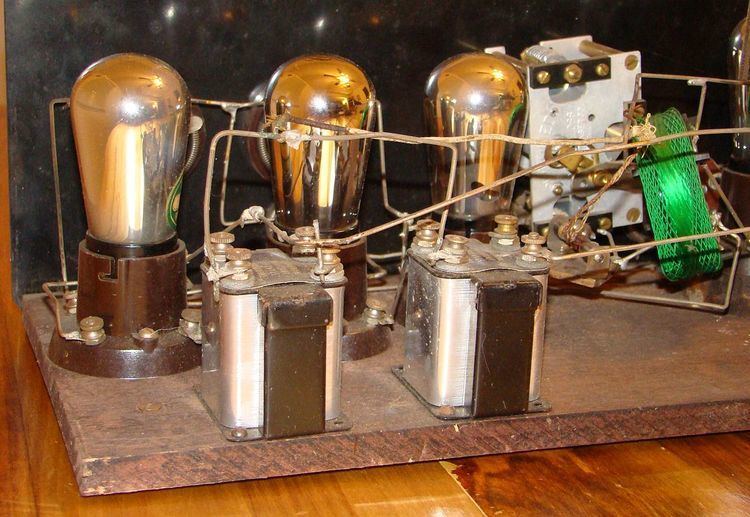
Antique TRF receivers can often be identified by their cabinets. They typically have a long, low appearance, with a flip-up lid for access to the vacuum tubes and tuned circuits. On their front panels there are typically two or three large dials, each controlling the tuning for one stage. Inside, along with several vacuum tubes, there will be a series of large coils. These will usually be with their axes at right angles to each other to reduce magnetic coupling between them.
A problem with the TRF receiver built with triode vacuum tubes was the triode's interelectrode capacitance. The interelectrode capacitance allowed energy in the output circuit to feedback into the input. That feedback could cause instability and oscillation that would frustrate reception and produce squealing or howling noises in the speaker. In 1922, Louis Alan Hazeltine invented the technique of neutralization that uses additional circuitry to partially cancel the effect of the interelectrode capacitance. Neutralization was used in the popular Neutrodyne series of TRF receivers. Under certain conditions, "the neutralization is substantially independent of frequency over a wide frequency band." "Perfect neutralization cannot be maintained in practice over a wide band of frequencies because leakage inductances and stray capacities" are not completely canceled. The later development of the tetrode and pentode vacuum tubes minimized the effect of interelectrode capacitances and could make neutralization unnecessary; the additional electrodes in those tubes shield the plate and grid and minimize feedback.
How it works
The classic TRF receivers of the 1920s and 30s usually consisted of three sections:
Each tuned RF stage consists of an amplifying device, a triode (or in later sets a tetrode) vacuum tube, and a tuned circuit which performs the filtering function. The tuned circuit consisted of an air-core RF coupling transformer which also served to couple the signal from the plate circuit of one tube to the input grid circuit of the next tube. One of the windings of the transformer had a variable capacitor connected across it to make a tuned circuit. A variable capacitor (or sometimes a variable coupling coil called a variometer) was used, with a knob on the front panel to tune the receiver. The RF stages usually had identical circuits to simplify design.
Each RF stage had to be tuned to the same frequency, so the capacitors had to be tuned in tandem when bringing in a new station. In some later sets the capacitors were "ganged", mounted on the same shaft or otherwise linked mechanically so that the radio could be tuned with a single knob, but in most sets the resonant frequencies of the tuned circuits could not be made to "track" well enough to allow this, and each stage had its own tuning knob.
The detector was usually a grid-leak detector, consisting of a triode tube biased near cutoff so it would only conduct on the positive half of the RF cycles. Some sets used a carborundum crystal detector (semiconductor diode) instead. Occasionally, a regenerative detector was used, to increase selectivity.
Some TRF sets that were listened to with earphones didn't need an audio amplifier, but most sets had one to three transformer-coupled or RC-coupled audio amplifier stages to provide enough power to drive a loudspeaker.
The schematic diagram shows a typical TRF receiver. This particular example uses six triodes. It has two radio frequency amplifier stages, one grid-leak detector/amplifier and three class ‘A’ audio amplifier stages. There are 3 tuned circuits T1-C1, T2-C2, and T3-C3. The second and third tuning capacitors, C2 and C3, are ganged together (indicated by line linking them) and controlled by a single knob, to simplify tuning. Generally, two or three RF amplifiers were required to filter and amplify the received signal enough for good reception.
Advantages and disadvantages
Terman characterizes the TRF's disadvantages as "poor selectivity and low sensitivity in proportion to the number of tubes employed. They are accordingly practically obsolete." Selectivity requires narrow bandwidth, but the bandwidth of a filter with a given Q factor increases with frequency. So to achieve a narrow bandwidth at a high radio frequency required high-Q filters or many filter sections. Achieving constant sensitivity and bandwidth across an entire broadcast band was rarely achieved. In contrast, a superheterodyne receiver translates the incoming high radio frequency to a lower intermediate frequency which does not change. The problem of achieving constant sensitivity and bandwidth over a range of frequencies arises only in one circuit (the first stage) and is therefore considerably simplified.
The major problem with the TRF receiver, particularly as a consumer product, was its complicated tuning. All the tuned circuits need to track to keep the narrow bandwidth tuning. Keeping multiple tuned circuits aligned while tuning over a wide frequency range is difficult. In the early TRF sets the operator had to perform that task, as described above. A superheterodyne receiver only needs to track the RF and LO stages; the onerous selectivity requirements are confined to the IF amplifier which is fixed-tuned.
During the 1920s, an advantage of the TRF receiver over the regenerative receiver was that, when properly adjusted, it did not radiate interference. The popular regenerative receiver, in particular, used a tube with positive feedback operated very close to its oscillation point, so it often acted as a transmitter, emitting a signal at a frequency near the frequency of the station it was tuned to. This produced audible heterodynes, shrieks and howls, in other nearby receivers tuned to the same frequency, bringing criticism from neighbors. In an urban setting, when several regenerative sets in the same block or apartment house were tuned to a popular station, it could be virtually impossible to hear. Britain, and eventually the US, passed regulations that prohibited receivers from radiating spurious signals, which favored the TRF.
Modern usage
Although the TRF design has been largely superseded by the superheterodyne receiver, with the advent of semiconductor electronics in the 1960s the design was "resurrected" and used in some simple integrated radio receivers for hobbyist radio projects, kits, and low-end consumer products. One example is the ZN414 TRF radio integrated circuit from Ferranti in 1972 shown below