
 | ||
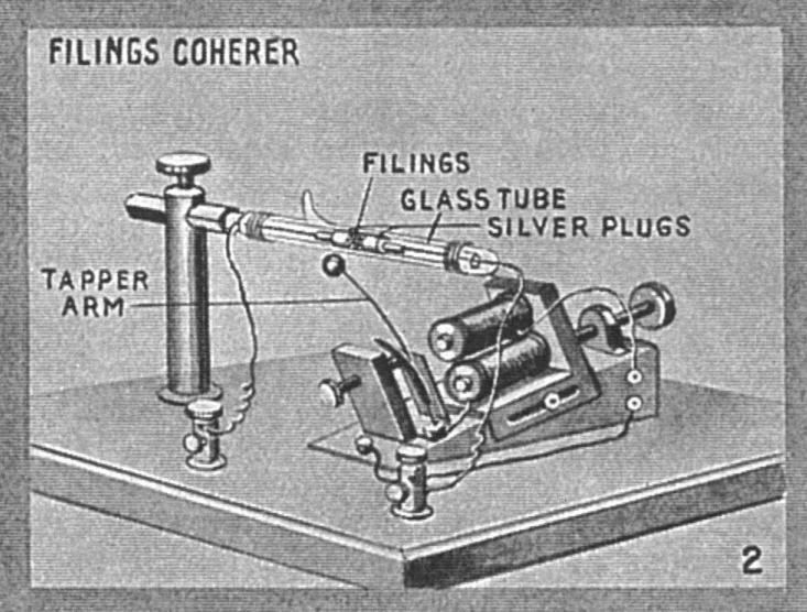
In electronics, a detector is an older term for an electronic component in a radio receiver that recovers information contained in a modulated radio wave. The term dates from the first three decades of radio (1886-1916). Unlike modern radio stations which transmit sound (an audio signal) on the radio carrier wave, the first radio transmitters transmitted information by wireless telegraphy, using different length pulses of radio waves to spell out text messages in Morse code. So early radio receivers did not have to extract an audio signal (sound) from the incoming radio signal, but only detect the presence or absence of the radio signal, to produce clicks in the receiver's earphones representing the Morse code symbols. The device that did this was called a detector. A variety of different detector devices, such as the coherer, electrolytic detector, and magnetic detector, were used during the wireless telegraphy era.
Contents
- Envelope detector
- Product detector
- Frequency and phase modulation detectors
- Phase detector
- The Foster Seeley discriminator
- Ratio detector
- Quadrature detector
- Other FM detectors
- Phase locked loop detector
- References
After sound (amplitude modulation, AM) transmission began around 1920, the term evolved to mean a demodulator, a nonlinear rectifier (usually a crystal diode or a vacuum tube) which extracted the audio signal from the radio frequency carrier wave. This is its current meaning, although modern detectors usually consist of semiconductor diodes, transistors, or integrated circuits.
In a superheterodyne receiver the term is also sometimes used to refer to the mixer, the tube or transistor which converts the incoming radio frequency signal to the intermediate frequency. The mixer is called the first detector, while the demodulator that extracts the audio signal from the intermediate frequency is called the second detector.
Envelope detector
One major technique is known as envelope detection. The simplest form of envelope detector is the diode detector that consists of a diode connected between the input and output of the circuit, with a resistor and capacitor in parallel from the output of the circuit to the ground to form a low pass filter. If the resistor and capacitor are correctly chosen, the output of this circuit will be a nearly identical voltage-shifted version of the original signal.
An early form of envelope detector was the cat's whisker, which was used in the crystal set radio receiver. A later version using a crystal diode is still used in crystal radio sets today. The limited frequency response of the headset eliminates the RF component, making the low pass filter unnecessary. More sophisticated envelope detectors include the plate detector, grid-leak detector and transistor equivalents of them, infinite-impedance detectors (peak detector circuits), and precision rectifiers.
Product detector
A product detector is a type of demodulator used for AM and SSB signals, where the original carrier signal is removed by multiplying the received signal with a signal at the carrier frequency (or near to it). Rather than converting the envelope of the signal into the decoded waveform by rectification as an envelope detector would, the product detector takes the product of the modulated signal and a local oscillator, hence the name. By heterodyning, the received signal is mixed (in some type of nonlinear device) with a signal from the local oscillator, to give sum and difference frequencies to the signals being mixed, just as a first mixer stage in a superhet would produce an intermediate frequency; the beat frequency in this case, the low frequency modulating signal is recovered and the unwanted high frequencies filtered out from the output of the product detector.
Product detector circuits are analog multipliers and so essentially ring modulators or synchronous detectors and closely related to some phase-sensitive detector circuits. They can be implemented using something as simple as ring of diodes or a single dual-gate Field Effect Transistor to anything as sophisticated as an Integrated Circuit containing a Gilbert cell.
Frequency and phase modulation detectors
AM detectors cannot demodulate FM and PM signals because both have a constant amplitude. However an AM radio may detect the sound of an FM broadcast by the phenomenon of slope detection which occurs when the radio is tuned slightly above or below the nominal broadcast frequency. Frequency variation on one sloping side of the radio tuning curve gives the amplified signal a corresponding local amplitude variation, to which the AM detector is sensitive. Slope detection gives inferior distortion and noise rejection compared to the following dedicated FM detectors that are normally used.
Phase detector
A phase detector is a nonlinear device whose output represents the phase difference between the two oscillating input signals. It has two inputs and one output: a reference signal is applied to one input and the phase or frequency modulated signal is applied to the other. The output is a signal that is proportional to the phase difference between the two inputs.
In phase demodulation the information is contained in the amount and rate of phase shift in the carrier wave.
The Foster-Seeley discriminator
The Foster-Seeley discriminator is a widely used FM detector. The detector consists of a special center-tapped transformer feeding two diodes in a full wave DC rectifier circuit. When the input transformer is tuned to the signal frequency, the output of the discriminator is zero. When there is no deviation of the carrier, both halves of the center tapped transformer are balanced. As the FM signal swings in frequency above and below the carrier frequency, the balance between the two halves of the center-tapped secondary is destroyed and there is an output voltage proportional to the frequency deviation.
Ratio detector
The ratio detector is a variant of the Foster-Seeley discriminator, but one diode conducts in an opposite direction, and using a tertiary winding in the preceding transformer. The output in this case is taken between the sum of the diode voltages and the center tap. The output across the diodes is connected to a large value capacitor, which eliminates AM noise in the ratio detector output. The ratio detector has the advantage over the Foster-Seeley discriminator that it will not respond to AM signals, thus potentially saving a limiter stage; however the output is only 50% of the output of a discriminator for the same input signal. The ratio detector has wider bandwidth but more distortion than the Foster-Seeley discriminator.
Quadrature detector
In quadrature detectors, the received FM signal is split into two signals. One of the two signals is then passed through a high-reactance capacitor, which shifts the phase of that signal by 90 degrees. This phase-shifted signal is then applied to an LC circuit, which is resonant at the FM signal's unmodulated, "center," or "carrier" frequency. If the received FM signal's frequency equals the center frequency, then the two signals will have a 90-degree phase difference and they are said to be in "phase quadrature" — hence the name of this method. The two signals are then multiplied together in an analog or digital device, which serves as a phase detector; that is, a device whose output is proportional to the phase difference between two signals. In the case of an unmodulated FM signal, the phase detector's output is — after the output has been filtered; that is, averaged over time — constant; namely, zero. However, if the received FM signal has been modulated, then its frequency will vary from the center frequency. In this case, the resonant LC circuit will further shift the phase of the signal from the capacitor, so that the signal's total phase shift will be the sum of the 90 degrees that's imposed by the capacitor and the positive or negative phase change that's imposed by the LC circuit. Now the output from the phase detector will differ from zero, and in this way, one recovers the original signal that was used to modulate the FM carrier.
This detection process can also be accomplished by combining, in an exclusive-OR (XOR) logic gate, the original FM signal and a square wave whose frequency equals the FM signal's center frequency. The XOR gate produces an output pulse whose duration equals the difference between the times at which the square wave and the received FM signal pass through zero volts. As the FM signal's frequency varies from its unmodulated center frequency (which is also the frequency of the square wave), the output pulses from the XOR gate become longer or shorter. (In essence, this quadrature detector converts an FM signal into a pulse-width modulated (PWM) signal.) When these pulses are filtered, the filter's output rises as the pulses grow longer and its output falls as the pulses grow shorter. In this way, one recovers the original signal that was used to modulate the FM carrier.
Other FM detectors
Less common, specialized, or obsolescent types of detectors include:
Phase-locked loop detector
The phase-locked loop detector requires no frequency-selective LC network to accomplish demodulation. In this system, a voltage controlled oscillator (VCO) is phase locked by a feedback loop, which forces the VCO to follow the frequency variations of the incoming FM signal. The low-frequency error voltage that forces the VCO's frequency to track the frequency of the modulated FM signal is the demodulated audio output.