
 | ||
In civil engineering and structural analysis Clapeyron's theorem of three moments is a relationship among the bending moments at three consecutive supports of a horizontal beam.
Contents
- Derivation of Three Moments Equations
- Mohrs First Theorem
- Mohrs Second Theorem
- The Sign Convention
- Derivation of Three Moment Theorem
- References
Let A,B,C be the three consecutive points of support, and denote by l the length of AB by
This equation can also be written as
where a1 is the area on the bending moment diagram due to vertical loads on AB, a2 is the area due to loads on BC, x1 is the distance from A to the centroid of the bending moment diagram of beam AB, x2 is the distance from C to the centroid of the area of the bending moment diagram of beam BC.
The second equation is more general as it does not require that the weight of each segment be distributed uniformly.
Derivation of Three Moments Equations
Mohr's Theorem can be used to derive the Three Moment Theorem (TMT).
Mohr's First Theorem
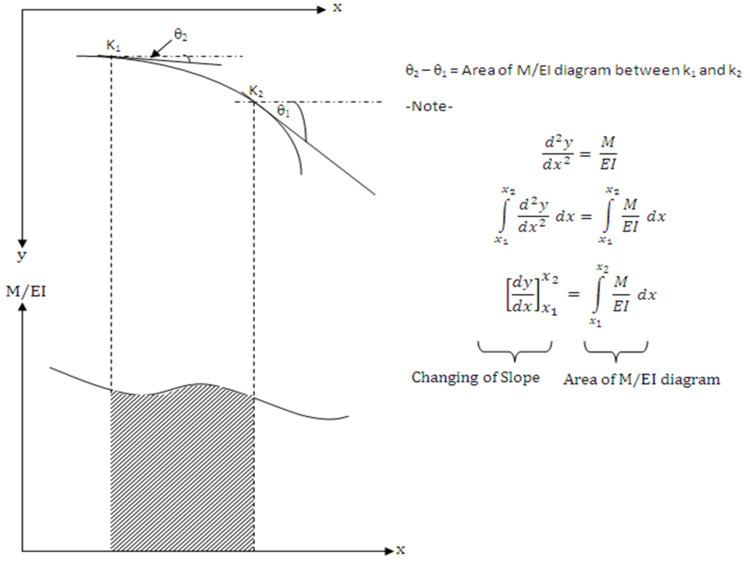
The change in slope of a deflection curve between two points of a beam is equal to the area of the M/EI diagram between those two points.(Figure 02)
Mohr's Second Theorem
Consider two points k1 and k2 on a beam. The deflection of k1 and k2 relative to the point of intersection between tangent at k1 and k2 and vertical through k1 is equal to the M/EI diagram between k1 and k2 about k1.(Figure 03)
Three Moment Equation expresses the relation between bending moments at three successive supports of a continuous beam, subject to a loading on a two adjacent span with or without settlement of the supports.
The Sign Convention
According to the Figure 04,
- The moment M1, M2, and M3 be positive if they cause compression in the upper part of the beam. ( Sagging positive)
- The deflection downward positive. (Downward settlement positive)
- Let ABC is a continuous beam with support at A,B, and C. Then moment at A,B, and C are M1, M2, and M3, respectively.
- Let A' B' and C' be the final positions of the beam ABC due to support settlements.
Derivation of Three Moment Theorem
PB'Q is a tangent drawn at B' for final Elastic Curve A'B'C' of the beam ABC. RB'S is a horizontal line drawn through B'. Consider, Triangles RB'P and QB'S.
From (1), (2), and (3),
Draw The M/EI diagram to find the PA' and QC'.
From Mohr's Second Theorem
PA' = First moment of area of M/EI diagram between A and B about A.
QC' = First moment of area of M/EI diagram between B and C about C.
Substitute in PA' and QC' on equation (a), Three Moment Theorem (TMT)can be obtain.