
Power type Electric Model Metrovick 1E | Build date 1923-1944 | |
 | ||
Builder Swiss Locomotive and MachineMetropolitan-VickersWerkspoorRobert Stephenson & Hawthorns Serial number SLM 2875-2934, 3655-3676WS 747-766RSH 7181-7190 | ||
The South African Railways Class 1E of 1925 was an electric locomotive.
Contents
- Railways electrification
- Benefits
- Colenso power station
- Manufacturers
- Characteristics
- Interior layout
- Orientation
- Bogies
- Traction motors
- Braking
- Sanding
- Lighting
- Service
- Modification
- Rebuilding
- Withdrawal
- Series specific data
- Illustration
- References
Between 1925 and 1945, the South African Railways placed altogether 172 Class 1E electric locomotives in service, spread over seven orders. They were the first mainline electric locomotives to be introduced in South Africa.
Railways electrification
In 1920, following a report and recommendations on electric traction by consulting engineers Merz and McClellan of London, the South African Parliament authorised the electrification of the lines between Durban and Pietermaritzburg in Natal and between Cape Town and Simon's Town on the Cape Peninsula, at a cost of £4,400,000.
At the time, there were two routes between Pietermaritzburg and Durban. The newer route with its 1 in 66 (1½%) gradients was chosen for electrification over the older route with its 1 in 33 (3%) gradients. Between Cato Ridge and Durban, electrification necessitated the doubling of the track and the construction of ten tunnels, as well as the construction of long stretches of cutting and embankment across difficult terrain.
After it was pointed out that the Natal traffic bottleneck was really above rather than below Pietermaritzburg, electrification in Natal eventually first took place between that city and Glencoe. It was a mountainous 171 miles (275 kilometres) single-track section which carried heavy mineral traffic towards the port of Durban on an alignment with severe gradients and tight curves, where the existing working by steam locomotives became too slow and inefficient to keep up with increasing traffic.
Work commenced in 1922 and the first electric train on that section was run in November 1925. The section was in full electric operation by January 1927. Electrification of the Simon's Town line commenced in March 1927 and full electric operation was introduced during September 1928.
Benefits
An important consideration in deciding upon the economics of electrification was the potential saving in wage-bills. Electrification would reduce the required crew roster from 300 drivers and firemen to 170 drivers and assistants. In addition, it was expected that a large reduction in overtime would be accomplished by increasing the average train speeds from steam traction's 8 miles per hour (13 kilometres per hour) to electric traction's 21 miles per hour (34 kilometres per hour) on the Glencoe to Pietermaritzburg section, with slightly higher future speeds anticipated. It was further estimated that the total capacity of the line would be increased by sixty per cent.
Colenso power station
The chosen overhead power supply was 3 kV DC, the highest direct current overhead voltage in use at the time. The Colenso power station was built by the SAR, specifically to power this line. The complete electrical system for the section consisted of the coal power station at Colenso, which generated three-phase 50 Hz current at 6.6 kV AC, stepped up and distributed at 88 kV AC to twelve automatic substations along the route. The substations were located at an average of about 15 miles (24 kilometres) apart and all but one were supplied at 88 kV by two separate three-phase transmission lines, while the one at Colenso was fed 6.6 kV AC directly from the power station.
At the substations, the current was stepped down again to 6.6 kV AC, converted by synchronous motor generators to 3 kV DC and fed to the overhead catenary, for use by the electric locomotives. The overhead equipment consisted of a copper catenary which supported a copper contact wire by means of droppers. The track structures were steel lattice masts, erected on concrete foundations.
Manufacturers
South Africa's first electric locomotive, the Class 1E, entered service in Natal in 1925. The locomotive was designed by Metropolitan-Vickers (Metrovick) of Manchester, while the mechanical parts of the unit were approved by Col F.R. Collins DSO, Chief Mechanical Engineer of the South African Railways (SAR). At the time, the first batch of 78 Class 1E, Series 1 locomotives constituted the largest order for a single type of electric locomotive to have been placed anywhere in the world. The eventual fleet of 172 locomotives was built for the SAR in seven series by four manufacturers over a period of twenty years.
Characteristics
The locomotives were operated as single units on light local passenger trains, double-headed on mainline passenger trains and light goods trains, or triple-headed on heavy goods trains.
Interior layout
The interior layout consisted of five compartments.
The sections of the roof above the compartments and the clerestory roof above the high tension compartment were removable to enable heavy machinery or control gear to be lifted out for repair.
Orientation
These dual cab locomotives had four grilles below the four windows on the equipment side, and only two grilles below the centre two windows on the corridor side. When observing the locomotive from the side with four grilles, the no. 1 end would be to the left.
Bogies
Like the subsequent Classes 2E, 3E and 4E, the Class 1E had bogie mounted draft gear. It had a Bo'Bo' wheel arrangement with an articulated inter-bogie linkage, therefore no train forces were transmitted directly to the locomotive body. The bogie pivot centres were 6,604 millimetres (21 feet 8 inches) apart. One of the bottom pivot centres was fixed, while the other was free to move longitudinally to allow for any wear occurring in the articulated coupling between the two bogies.
Traction motors
The four-pole traction motors each operated at 1.5 kV. They were electrically coupled in pairs, two in series across the 3 kV supply line.
Braking
The locomotive used air brakes. Air connections between units were arranged in the main reservoir circuit, so that air could be supplied to another unit in the event of failure of its compressor. For train braking, it also made use of regenerative braking, which enabled higher speeds to be allowed on down grades, while reducing the dependence on the train's vacuum or air braking system and with the collateral benefit of savings in electricity consumption. The usual speeds during regeneration were 14 and 28 miles per hour (23 and 45 kilometres per hour) for goods and passenger working, respectively. It was reportedly the first extensive use, in regular traffic, of electric locomotives equipped for multiple unit operation with regenerative braking.
Sanding
Sanding was arranged for multiple control with electrically operated sand valves, to enable multiple unit coupled locomotives to sand simultaneously.
Lighting
Lighting was supplied from a 110 V circuit, which was fed by the 16 kilowatts (21 horsepower) generator in parallel with 110 V lead acid batteries. The batteries were mounted in cases, hung underneath the locomotive body between the bogies. This generator also supplied power to the control circuits, exhauster, compressor and cab heaters.
Service
While they were employed mainly in Natal, some later also worked on the Witwatersrand and eventually also in the Western Cape. Some of them covered more than 8,000,000 kilometres (5,000,000 miles) during their service lives.
Early models bore number plates inscribed in English only. By 1938, when the Series 5 locomotives were placed in service, Afrikaans had been accepted as South Africa's second official language and new locomotives bore bilingual number plates.
Modification
They served in both goods and passenger service. Since their top speed of 72 kilometres per hour (45 miles per hour) was considered too slow for fast passenger service on the mail trains, two Class 1E units, numbers E121 and E122, were modified in 1936 by changing their gear ratio to enable them to run at speeds of up to 90 kilometres per hour (56 miles per hour). This appeared to be the practical limit for this type of electric locomotive.
Rebuilding
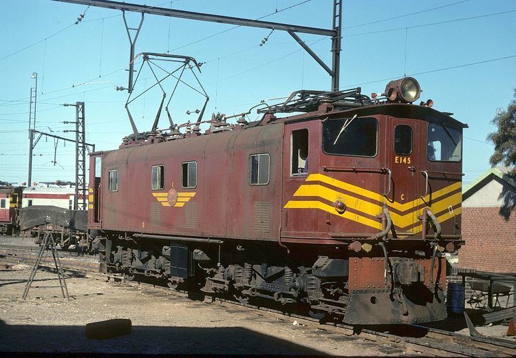
Altogether 35 of the Class 1E locomotives were eventually withdrawn from mainline service, modified and reclassified to Class 1ES, for use as shunting locomotives. The modifications included alteration of the resistance grids in the electrical circuit and enlarged and widened cabs, but the gear ratios were not altered. Apart from the wider cabs, the modified Class 1ES locomotives were identifiable by their front windows with slanted upper edges, compared to the rectangular shaped front windows of the Class 1E.
In 1964, two of these Class 1ES locomotives were rebuilt to centre-cab Class ES shunting locomotives.
Withdrawal
All the Class 1E and Class 1ES locomotives were withdrawn from service by 1990.
Series-specific data
The Class 1E builders, works numbers, years of construction and modifications to Classes ES and 1ES are listed in the table. The axle load and adhesive weight, as shown under "Specifications" in the infobox table, may be considered as average figures for the Class 1E, since these weights varied between the seven locomotive series. In respect of the Series 1 to 6 locomotives, the actual load per axle of each bogie and the total locomotive mass are included in the table below.
Illustration
The main picture shows a Class 1ES locomotive with its enlarged cab and slanted upper edge front windows, while the following pictures illustrate unmodified locomotives.